
The VEVOR sliding gate opener is a reliable and efficient product that can make your life easier. However, before installing and operating it, it’s important to read the manual and understand how to use it safely and efficiently. In this comprehensive gate opener manual, we’ll walk you through the installation process and provide you with all the information you need to use your VEVOR sliding gate opener effectively.
Table of contents
Dear users,
Thank you for choosing this product. Please read the manual carefully before assembling and using it.
Please do not leave out the manual if you send this product to a third party.
Safety Instruction
Please ensure that the power voltage matches with the supply voltage of the gate opener (AC110V or AC220V); kids are forbidden to touch the control devices or the remote-control unit.
The remote-control unit is controlled by a single-button mode. The indicator light on the remote control unit will flicker when the button on it is pressed. The main engine and gate can be unlocked by disengagement wrench and the gate can move with manual operation after disengagement.
Please ensure that no one is around the main engine or gate when the switch Is operated and it is usually demanded to examine the stability of installation. Please temporarily stop using if the main engine needs repair or regulation.
The installation and maintenance of the products must be carried out by professionals.
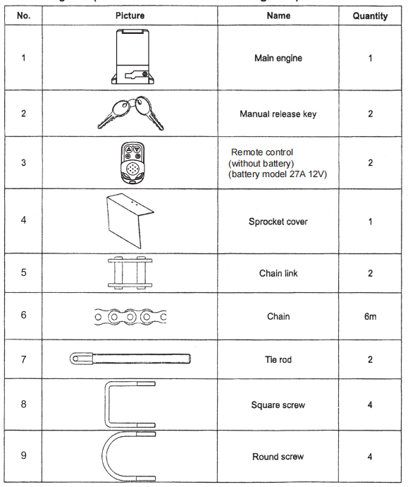
Packing List (standard/detachable mounting base)
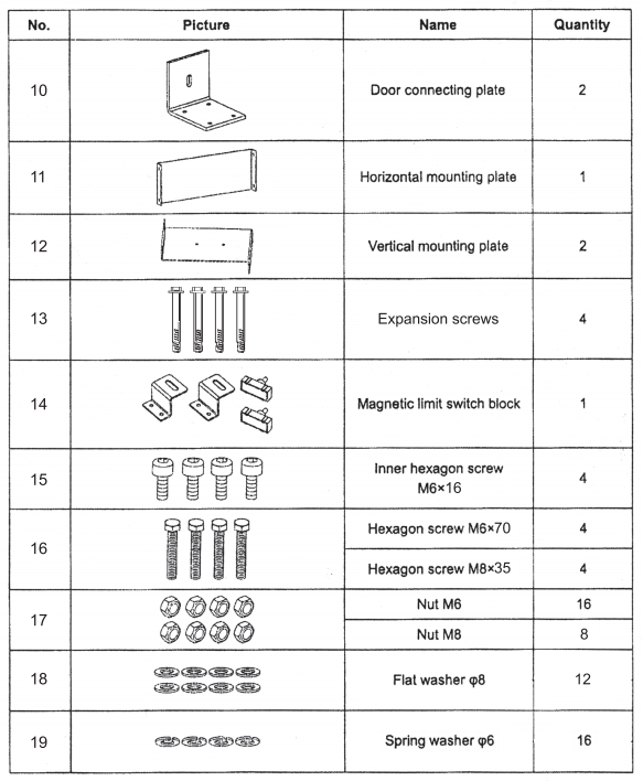
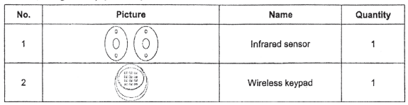
Packing List (optional)
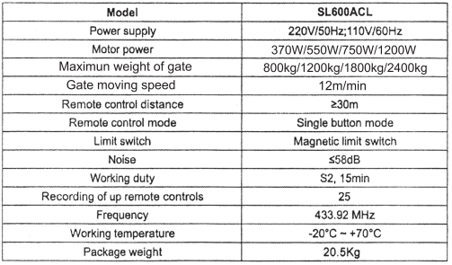
Technical Parameters
Installation
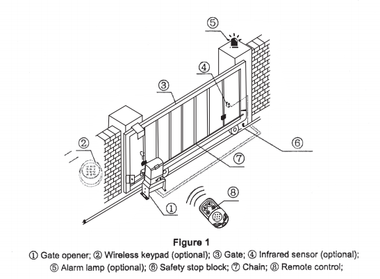
SL600ACL sliding gate opener is applicable to gate weight less than 600kg, and the length of the sliding gate should be less than 8m. The drive mode adopts the sprocket and chain transmission. This gate opener must be installed inside the enclosure or yard for protection.
Installation Drawing
Size of main engine and accessories
Size of main engine
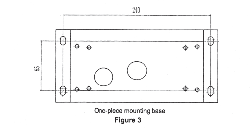
Size of embedded hole
Installation procedures
Preparation work before installation
Please ensure that the sliding gate is correctly installed, the gate rail is horizontal, and the gate can glide back and forth smoothly when moved by hand before installing the gate opener.
Cable installation
Please bury the motor & power cable and controlling cable with a PVC tube, and use two PVC tubes to bury (the motor & power cable)and (controlling cable)separately, to guarantee normal operation of the gate opener and protect the cables from damage.
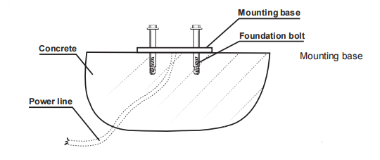
Concrete pedestal
Please cast a concrete pedestal with a size of 500 mm x 350 mm and depth of 200mm in advance, to firmly install the SL600ACL gate opener. Please verify whether the distance between the gate and gate opener is suitable before casting the pedestal.
Embedded screws
Main engine installation
a) Dismantle the plastic housing on the main engine before installation and keep relevant fasteners properly;
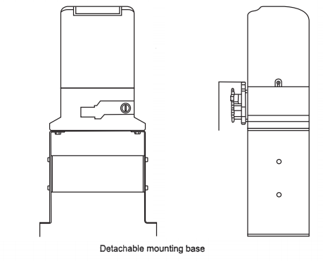
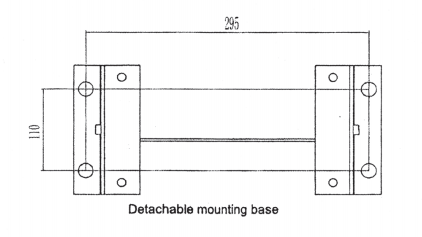
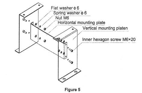
b) If select the detachable mounting base, the base should be assembled first as shown in Figure 5;
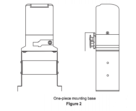
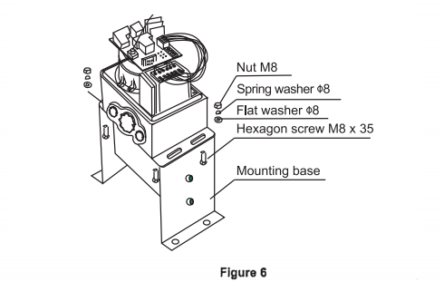
c) Assemble the machine engine to the mounting base as shown in Figure 6;
d) Please prepare the power line for connecting the mounting plate and main engine (the number of power supply cable cores shall not be less than 3 PCS, the sectional area of cable core shall not be lower than 1.5 mm²and the length shall be determined by users according to the field situation) due to different installation environments;
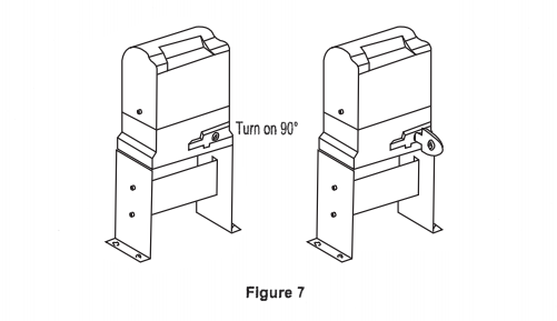
e) Please unlock the main engine before installation, the unlock method is: to take out the key cover, insert the key, and open the manual release bar till it rotates by 90°as shown in Figure 7. Then turn the output sprocket and the sprocket can be rotated easily;
Chain installation
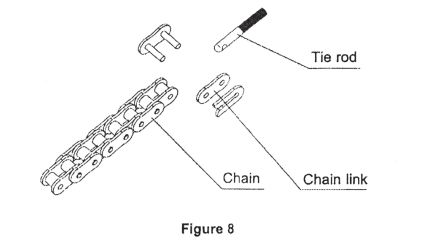
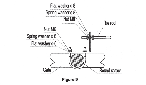
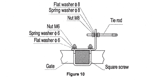
Close the gate; connect the tie rod with the chain through the chain link; fasten the tie rod to the door connecting plate by washers and nuts as shown in Figure 8. If necessary, the elasticity of the chain can be adjusted through the tie rod at both ends as shown in Figures 9 and 10.
If necessary, the chain can be shortened. If it needs to be lengthened, make sure to use the same type of chain.
If the door frame is round, please use the round screw as shown in Figure 9:
If the door frame is square, please use the square screw as shown in Figure 10:
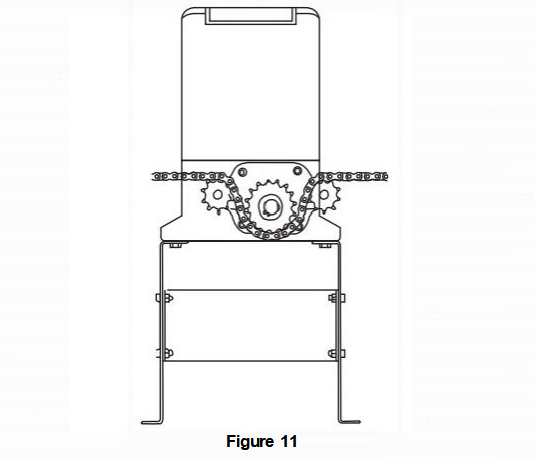
Installation of chain, small and big sprocket as shown in Figure 11:
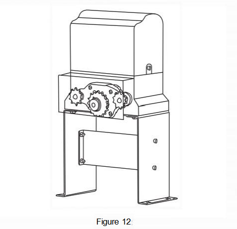
Installation of sprocket cover as shown in Figure 12:
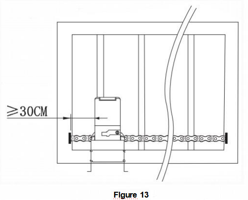
The distance between the main engine and chain ends should be at least 30CM, as shown in Figure 13:
Warnings
- To ensure safety, install safety stop blocks on both ends of the rails to prevent the gate out of the rail.
Before installing the main engine, make sure that the safety stop blocks are in place and that it has the function of preventing the gate from moving out of the rail and out of the safety range.
- Please ensure that the main engine and its components have good mechanical properties, and the gate can operate flexibly when moved by hand before installing the main engine.
- Earth leakage circuit breaker must be installed where the gate movement can be seen, and the minimum mounting height is 1.5m to protect it from being touched.
- After installation, please check whether the mechanical property is good or not, whether gate movement after manual unlocking is flexible or not, and whether the infrared sensor (optional)is installed correctly and effectively.
Limit switch adjustment
Use the manual release key to unlock the gate opener and manually move the gate to the predetermined position; fix the magnetic limit switch block and close the clutch; testing run after power on, slightly adjust the position of the magnetic limit switch block until the gate reaches the desired open and close limit location.
Installation of magnetic limit switch bock:
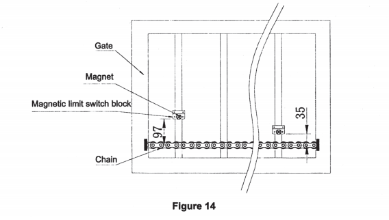
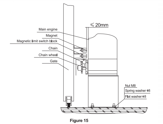
Note: The default setting is right-side mounting. (According to the situation, please refer to the “Note” of section “Adjustment and operation” to adjust)
Conclusion
We hope that our comprehensive manual and PDF guide have provided you with all the necessary information to install and use your VEVOR Sliding Gate Opener safely and efficiently. By following our step-by-step instructions and safety guidelines, you can enjoy the convenience of your sliding gate opener for years to come. Remember to always prioritize safety and seek professional help when necessary.


