
Step into a realm of seamless security with the VEVOR sliding gate opener manual. This guide, spanning installation, safety instruction, packing list, and technical parameters, is your key to unlocking effortless gate operation. Join us on a journey where VEVOR technology meets simplicity, making your property smarter and safer. Let’s dive into the future of gate automation.
Table of contents
Safety Instruction
Please ensure that the using power voltage matches with the supply voltage of gate opener (AC110V orAC220V); kids are forbidden to touch the control devices or the remote-control unit.
The remote-control unit is controlled by a single button mode. The indicator light on the remote-control unit will flicker when the button on it is pressed. The main engine and gate can be unlocked by disengagement wrench and the gate can move with manual operation after disengagement.
Please ensure that no one is around the main engine or gate when the switch Is operated, and it is usually demanded to examine the stability of installation. Please temporarily stop using if the main engine needs repairing or regulation.
The installation and maintenance of the products must be carried out by professionals.
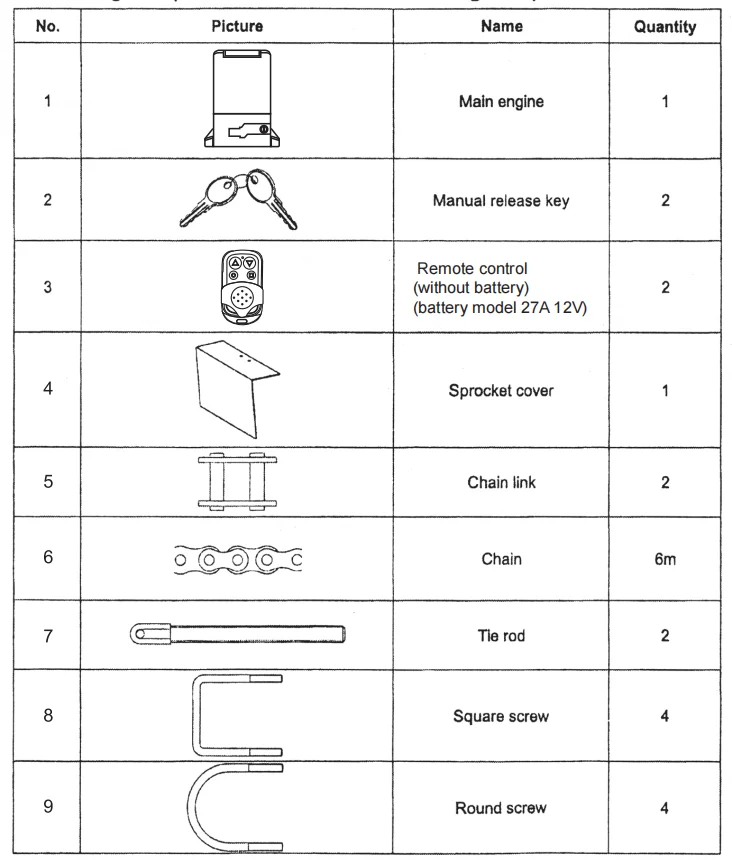
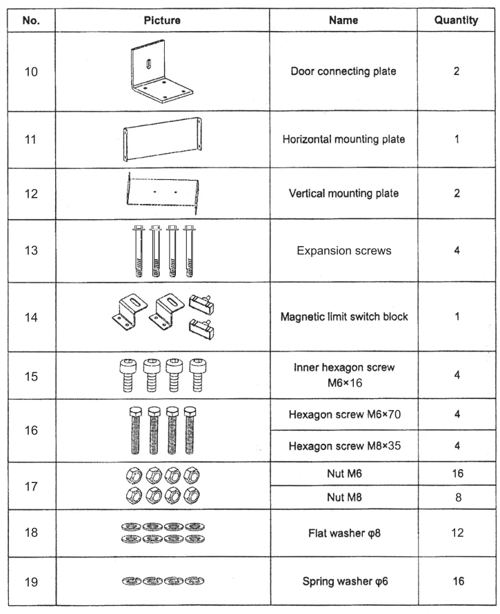
Packing List (Standard 丨Detachable mounting base)
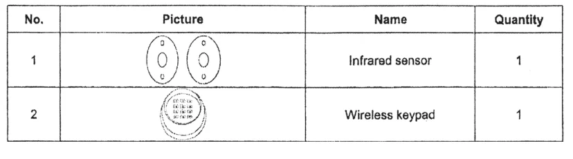
Packing List (optional)
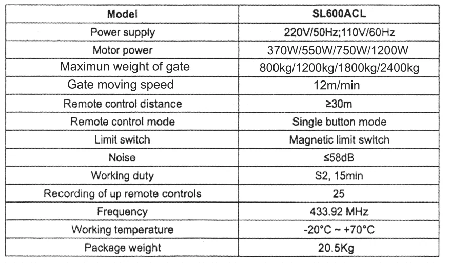
Technical parameters
Installation
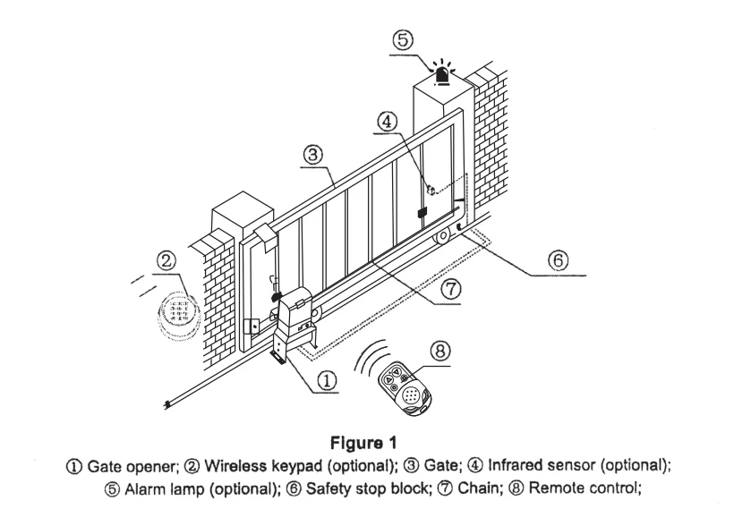
SL600ACL sliding gate opener is applicable to gate weight less than 600 kg, and length of the sliding gate should be less than 8m. The drive mode adopts the sprocket and chain transmission. This gate opener must be installed inside the enclosure or yard for protection.
Installation drawing
Size of main engine and accessories
Size of main engine
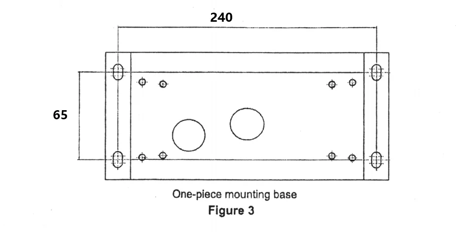
Size of embedded hole
Installation procedures
Preparation work before installation
Please ensure that the sliding gate is correctly installed, the gate rail is horizontal, and the gate can glide back and forth smoothly when moved by hands before installing the gate opener.
Cable installation
Please bury the motor power cable and controlling cable with PVC tube, and use two PVC tubes to bury (motor power cable)and (controlling cable)separately, so as to guarantee normal operation of the gate opener and protect the cables from damages.
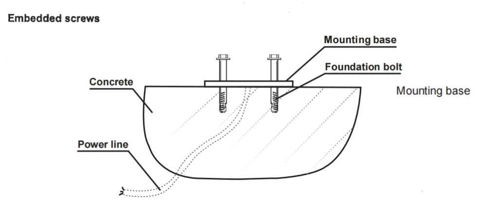
Concrete pedestal
Please cast a concrete pedestal with the size of 500mmx350mm and depth of 200 mm in advance, so as to firmly install SL600ACL gate opener. Please verify whether the distance between the gate and gate opener is suitable before casting the pedestal.
Main engine installation
- Dismantle the plastic housing on the main engine before installation and keep relevant fasteners properly;
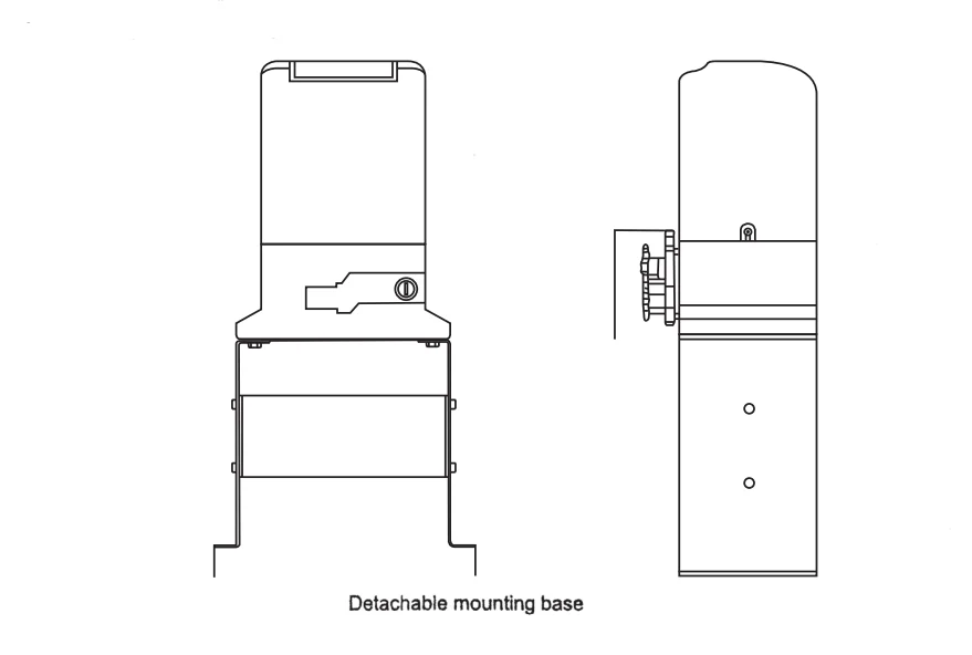
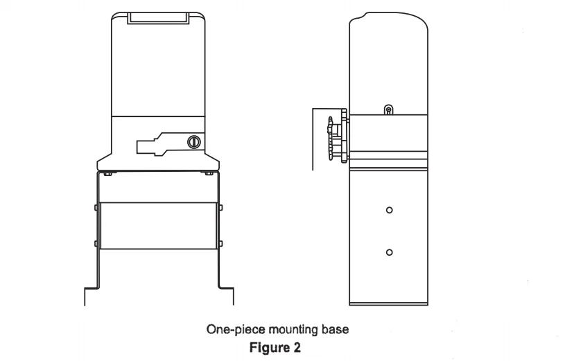
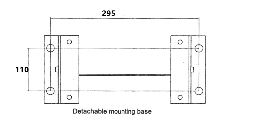
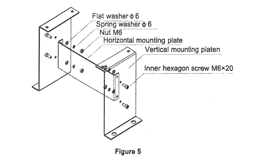
- If select the detachable mounting base, the base should be assembled first as shown in Figure 5;
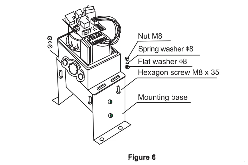
- Assemble the machine engine to the mounting base as shown in Figure 6;
- Please prepare the power line for connecting mounting plate and main engine (the number of power supply cable core shall not be less than 3 PCS, the sectional area of cable core shall not be lower than 1.5 mm²and the length shall be determined by users according to the field situation)due to different installation environments;
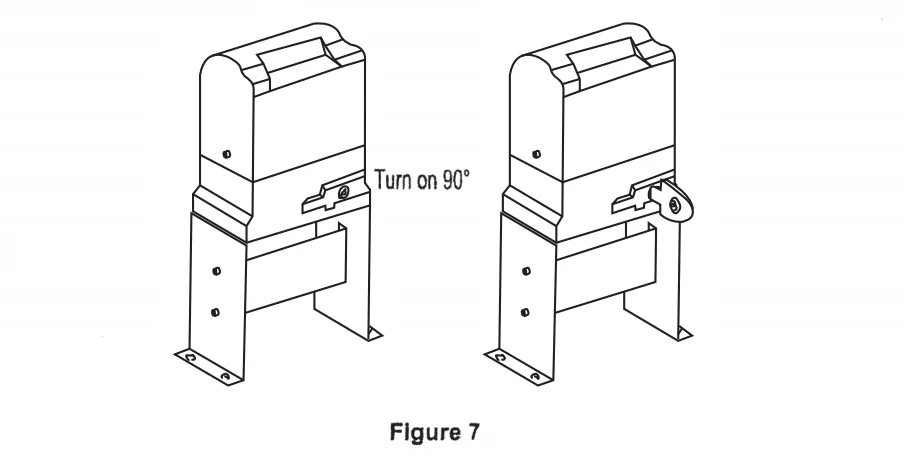
- Please unlock the main engine before installation, the unlock method is: take out the key cover, insert the key, and open the manual release bar till it rotates by 90°as shown in Figure 7. Then turn the output sprocket and the sprocket can be rotated easily;
Chain installation
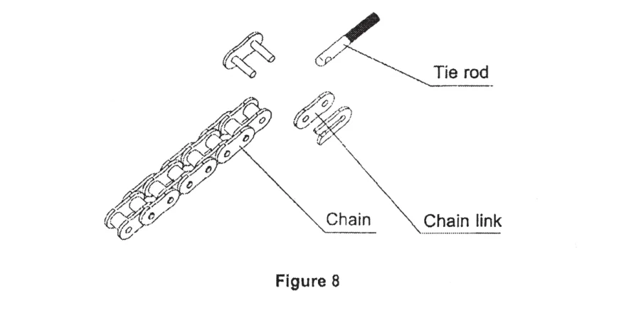
Close the gate; connect the tie rod with chain through chain link; fasten the tie rod to the door
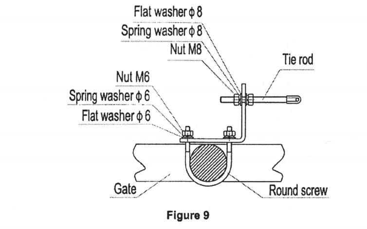
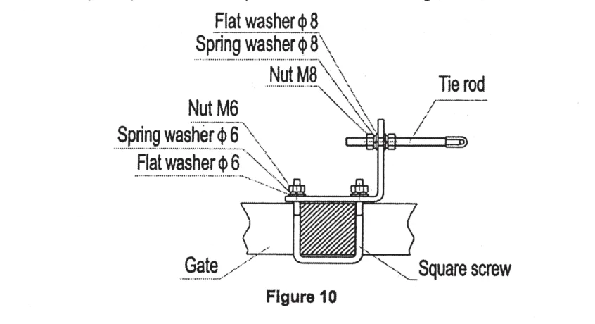
connecting plate by washers and nuts as shown in Figure 8. If necessary, the elasticity of the chain can be adjusted through the tie rod at both ends, as shown in Figure 9 and 10. If necessary, the chain can be shortened. If it needs to be lengthened, make sure lo use the same type of chain.
If the door frame is round, please use the round screw as shown in Figure 9:
If the door frame is square, please use the square screw as shown in Figure 10:
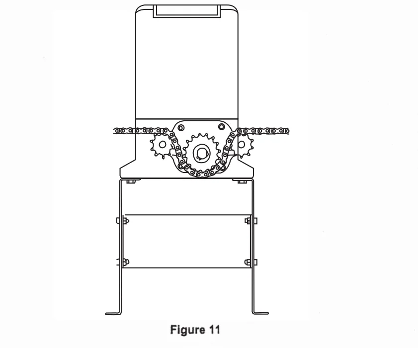
Installation of chain, small and big sprocket as shown in Figure 11:
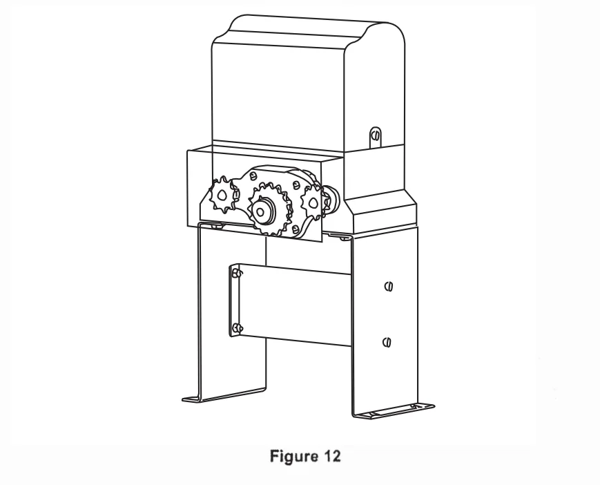
Installation of sprocket cover as shown in Figure 12:
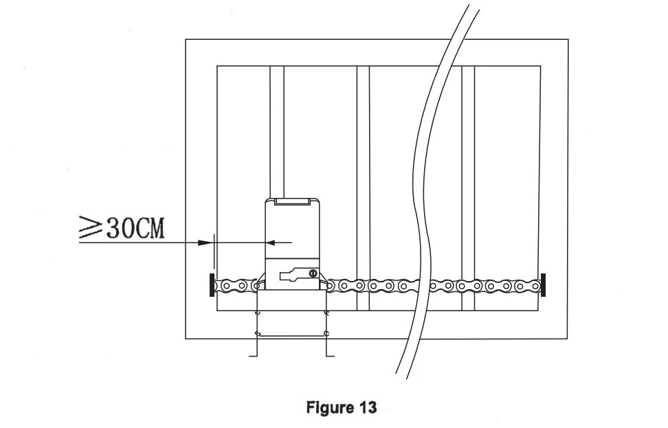
The distance between main engine and chain ends should beat least 30CM, as shown in Figure 13:
Warnings
- To ensure safety, install safety stopblocks on both ends of the rails to prevent the gate out of the rail. Before installing the main engine, make sure that the safety stop blocks are in place and whether it has the function of preventing the gate from moving out of the rail and out of the safety range.
- Please ensure that the main engine and its components have good mechanical properties, and the gate can operate flexibly when moved by hands before installing the main engine.
- In this product, one control can drive one main engine only, otherwise, the control system will be damaged.
- Earth leakage circuit breaker must be installed where the gate movement can be seen, and the minimum mounting height is 1.5m to protect it from being touched.
- After installation, please check whether the mechanical property is good or not, whether gate movement after manual unlocking is flexible or not, and whether the infrared sensor (optional)is installed correctly and effectively.
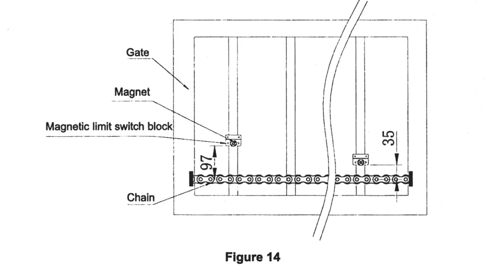
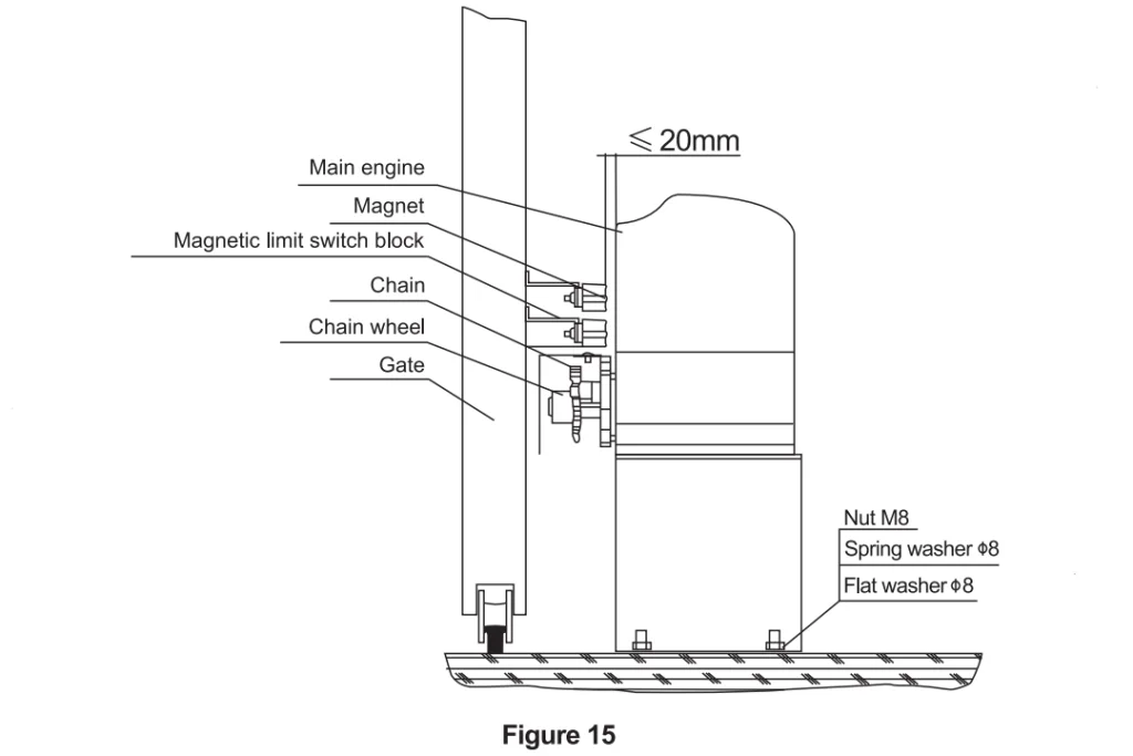
Limit switch adjustment
Use the manual release key to unlock the gate opener and manually move the gate to the
predetermined position; fix the magnetic limit switch block and close the clutch; testing run after power on, slightly adjust the position of the magnetic limit switch block until the gate reaches the desired open and close limit location.
Installation of magnetic limit switch block:
FAQs
Q1: How challenging is the installation process?
A1: Installing your VEVOR Sliding Gate Opener is surprisingly straightforward. Follow the step-by-step instructions in the manual, and you’ll have it up and running in no time.
Q2: Are there safety precautions to consider?
A2: Absolutely. The manual provides comprehensive safety instructions to ensure a secure and worry-free operation of your sliding gate opener.
Q3: What’s included in the packing list?
A3: The packing list is designed for your convenience. Find all the necessary components neatly listed, making your installation process smooth and efficient.
Q4: What are the technical parameters of the Sliding Gate Opener?
A4: The manual details the technical specifications, providing you with insights into the power, speed, and other crucial parameters of your VEVOR Sliding Gate Opener.
Summing Up
To wrap up, the VEVOR Sliding Gate Opener Manual is more than a guide; it’s a gateway to a secure, technologically advanced future. From the initial installation to the personalized technical nuances, every section echoes our dedication to excellence. Elevate your property’s security, transform your daily routine, and embrace the ease of VEVOR innovation. Don’t just secure your gate; redefine it. Take charge of your space with VEVOR – where cutting-edge technology meets unparalleled reliability. Your journey to a smarter, safer home begins here. Act now and experience the VEVOR advantage!


