
Welcome to the world with VEVOR diesel heater installation, where convenience meets excellence. VEVOR diesel heater manual unfolds the step-by-step process, ensuring you master the art of Main Heater Installation, Air Heating System Setup, Fuel Supply System Integration, Fuel Pump Installation, and Fuel Filter Incorporation. Elevate your space with VEVOR’s precision-engineered heaters, offering not just warmth but a seamless installation experience.
Join us as we guide you through every detail, making your comfort our priority. Don’t just heat; elevate with VEVOR. Your comfort, our commitment. Let’s get started!
Table of contents
Introduction
Application field of Air heater
The air heater is not affected by the engine, and it is supplied for the following vehicles with corresponding power
- All kinds of auto and trailers.
- Constructiormachinery
- Agricultural machinery
- Boat, ship, yacht
- Caravan
Function
- Warm-up, defrost glass
- Heat and keep warm for the followed area:
-Driving cab, cabin
-Cargo hold
-Interior of staff carrier
-Caravan
The heater can not be used on followed place and situation
- Constant heating for long time:
-Living room, garage
-Residential purpose boat - Heat and dry:
-Life (people, animal), blowing hot air directly
-Articles and objects
-Blow hot air to container
Heater Safety instruction of installation and operation
Installation
Prevent the substances around heater from being damaged and influenced by high temperature.
Exhaust emission system
When put the exhaust vent, prevent the exhaust entering the heating space through ventilator, hot air inlet and window. Keep the exhaust pipe clear. The exhaust pipe outlet shall be kept away from anything flammable, and avoid heating and igniting the flammable goods and loading cargo on the ground.
The air inlet of combustion-supporting air
The combustion-supporting air which is used for heater burning shall not be inhaled from passenger compartment. The air inlet shall not be blocked, and keep the inlet open and clear. If the air inlet equipped with filter, keep the filter clean regularly.
The heating air inlet
The heater air shall be composed by fresh air or circulating air, which is inhaled from clean area. The air inlet pipe shall be protected by a safety fence or other suitable tools, and keep the pipe clear and open.
The heating air outlet
In order to prevent the people and goods from being damaged, the hot air pipe shall be installed in the place where it couldn’t be access to easily.
Safety Instruction
The following measures shall not be adopted
-Change the important component of the heater
-Make use of spare parts from other manufacturers without permission
-Disobey the instruction and guide during installation or operation
Only allow the use of original attachment and spare parts during installation and maintenance.
The heaters shall not be used in places where may form flammable vapor dust, for example:
-Fuel depot
-Carbon storehouse
-Timber storehouse
-Granary and similar sites
-Diesel/petrol station
The heaters shall be turned off when fill fuel.
If the fuel leaks or discharges from the fuel system of heaters, please contact the service provider to repair
In the process of work, it is forbidden to cut off the electric power directly to stop the heater from working.
Product
Survey
KW2.0 Air heater (hereafter referred to as the heater)is independent to the original engine system, it makes use of 12V or 24V direct current to drive. There are two kinds of control modes of the heater: Automatic control mode and Manual control mode. The heater adopts light diesel and gasoline which corresponds to the environmental temperature as fuel, and it can be started and operated normally at a temperature of above 40 N. The inhaled fresh air is heated to hot air through a heat exchanger by the energy which comes from fuel burning, then blown to where it is needed. This type of heater has the advantage of compact structure, light weight, high thermal efficiency, economize on electricity and fuel, and easy installation.
Technical specification
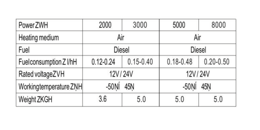
Structural principle
After the heater starts, the glow plug comes into operation, the magnetic pump begins to supply fuel, the combustion-supporting fan inhales combustion-supporting air from outside of the car. The fuel generates the heat by burning in the combustion chamber, which is taken by aluminum heat exchanger. The inner air pushed by the heat exchange fan brings heat to where it is needed through the surface of heat exchanger. And the combustion emission is discharged through exhaust pipe.
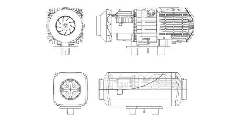
The structure of hood-shape case
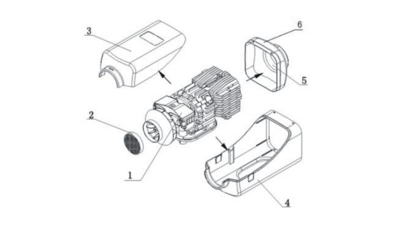
1-Main engine; 2-Suction hood; 3-Upper hood; 4-Bottom-hood; 5-Air outlet; 6-Rear hood {Hood: Case/Shell}
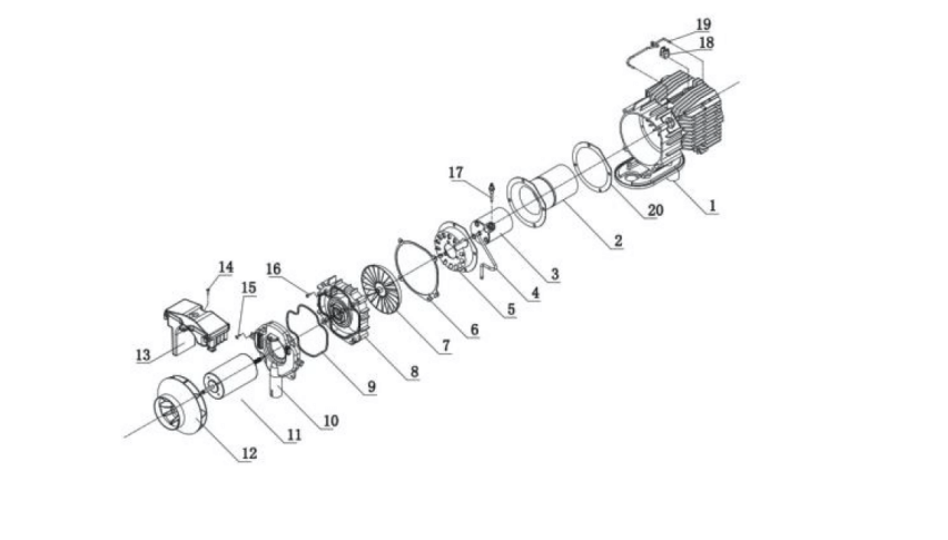
- Exhaust tube;
- Combustion pipe;
- Combustor;
- Fuel tube;
- Air inlet distributor;
- Gasket;
- Combustion supporting fan blades;
- Bracket of fan motor;
- Gasket;
- Combustion supporting air inlet;
- Fan motor
- Blade wheel of heating fan;
- Main control panel;
- Fixing screw;
- Fixing screw;
- Fixing screw;
- Igniter;
- Heat sensor;
- Sensor Fixed bracket
Installation
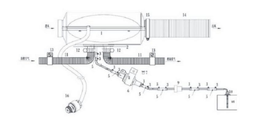
Only special-purpose parts can be used for installation of the heater. Following picture is the diagram for installation.
The positions and ways of fixing of various parts may vary from one automobile model to another, but the general principles must be followed in conformity with the requirements of this chapter. Otherwise, the heater may not work normally or safety problems my occur.
Main heater installation
The main heater could be installed both inside and outside of the vehicle. If the heater is installed outside the vehicle, measures must be taken to avoid splashing water onto the heater. Enough space must be provided for installation for the convenience of heating air flow and installation, maintenance of the main heater.
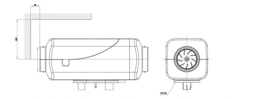
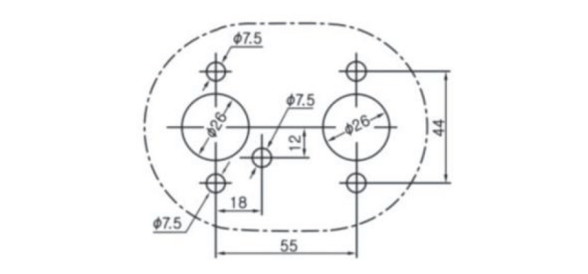
Good sealing is necessary between the main heater and the installation surface on the vehicle. The special gasket supplied by the manufacturer must inserted in. And the installation surface must be even. Its parts at the installation bases of the main heater should have uneveness less than 1 mm. After drilling installation holes, eveness must be improved according to this requirement. At installation, please rotate the four M6 nuts tight, which are provided by the manufacturer.
For re-installation of the main heater, a new gasket must be used to replace the old one.
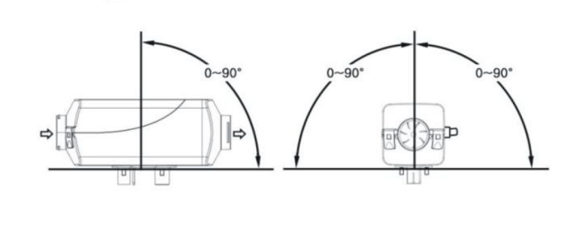
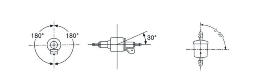
Attention must be paid to that the inclination angle shall not exceed the limit, or normal operation will be affected. Direction for installation of the main heater is shown in the following picture.
After installation of the main heater, please check and make sure that there is no contactor friction between the blade wheel of fan and other nearby parts to avoid unsmooth operation.
Installation of Air Heating System
The air heating system of the heater should not be connected with the air channel of the vehicle. Either independent outer circulator inner circulation mode can be adopted.
When an external heating air tube is attached to the heater, the tube diameter should not be smaller than 85mm. Its material should be capable to resist temperature of 130NE.
The maximum pressure drop between the air inlet side and outlet side of the air heating system should not be higher than 0.15kPa.
The hot air from the heating system should not erupt onto such parts which are unable to resist heat. In passenger vehicles, the hot air vent should not be blocked by passengers. A self-provided protective net can be installed if necessary.
For heater working in external circulation mode, the position of air inlet port should be proper to guaranteed that under normal operation no splash of water can be sucked into the heater the no exhaust from the engine can be sucked in.
For heater working in internal circulation, measures should be taken to avoid re-entering of the supplied hot air into the air inlet port. If no air inlet tube is attached in this mode, an air inlet hood with grids must be installed at the air inlet port of the main heater. The inlet air should be drawn from the cold area of the compartment, such asunder the seats or berths.
Installation of Fuel Supply System
Fuel for the heater can be supplied from the fuel tank of the vehicle or an additional independent fuel tank. It is not allowed to install the fuel tank in the cab or passenger compartment or any region that is possibly to cause fire if an independent fuel tank is used.
The elevation difference between the heater and fuel pump, and between the fuel pump and the fuel pump produces pressure from fuel to the fuel pump. The inner diameter and length of the fuel tube is related to the resistance of the fuel route. Please consider such factors for installation.

Fuel pump installation
The fuel pump should be installed in places that can avoid heat radiant from the vehicle parts that can emit heat and in places with cool air. Its ambient temperature should not exceed 20 N. Directions of installation of the fuel pump are shown in the following picture. When installing the fuel pump, please use the fuel pump holder supplied with the heater to hold the pump tight. The pump is fixed with the shock-reducing tightening piece.
Fuel Filter installation
The fuel filter should be installed before the fuel inlet port. Please make sure that the fuel flow is correctly followed.
Its position shall be in conformity with the above picture.
Installation of Fuel Tube
Only the flexible nylon tube, which has good light-resistance and thermal stability, supplied with the heater can be used as the fuel tube. The inner diameter of the tube is Ї 2 mm.
The position of fuel tube should be against flying stones and be away from any heat emitting parts of the vehicle. Protective device can be installed if necessary.
The fuel tube from the fuel pump to the main heater should be in any directions other than downward direction. The fuel tube shall be tied in some proper location to make it fixed.
The distance between two ties shall be less than 50 cm.
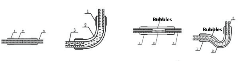
The fuel tube fittings supplied with the heater should be used for connections between fuel tube and fuel pump, fuel tube and heater, fuel tube and sucking tube of fuel tank and fuel tube and reducing T. The fuel tube should tie with fuel tube clamps. Bubbles should be eliminated from the connecting places.
1. Fuel tube clamp; 2-Fueltubefitting; 3-Fuel tube
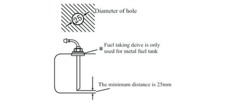
Installation of Fuel Taking Device
The openings on the fuel tank (or tank cover)for installation should be appropriate in size, with trimmed brim and with good eveness around the opening. Good sealing is necessary for the base of the fuel taking tube. The bottom end of the fuel taking tube should be 30 mm-40 mm from the bottom of fuel tank to suck enough fuel and at the same time to avoid sucking in impurities sediment on the bottom of fuel tank.

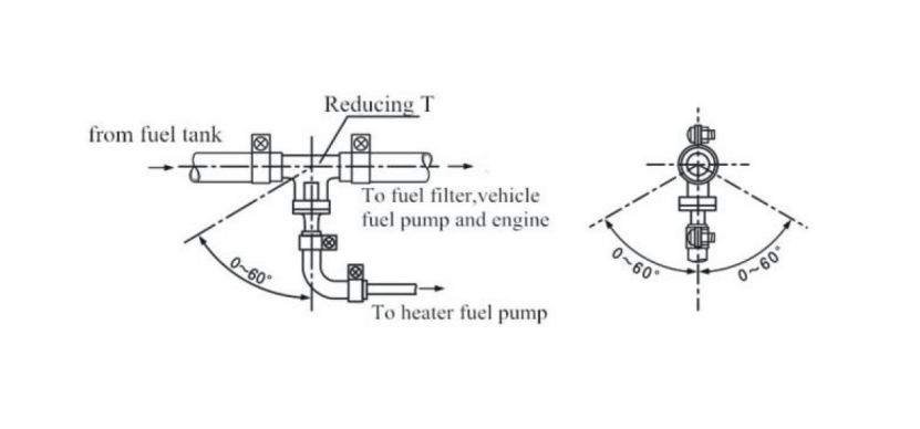
If fuel is taken from the fuel pipe to the engine, the fuel pipe from the fuel tank to the fuel filter should be disconnected and re-connected with the thicker pipes of the reducing T. And the thinner pipe of the reducing T should connect the fuel pump of the heater via fuel tube fitting and tube. The angle of installation must in conformity with following picture, or normal work of the heater will be affected.
After installation, the vehicle engine shall be started and then turned off after one minute work to eliminate air trapped in the fuel sucking pipe.
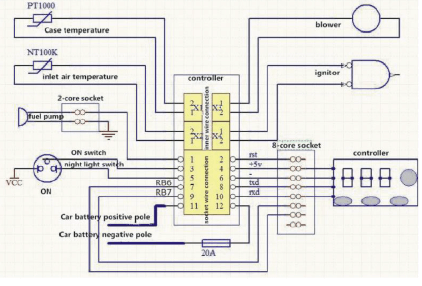
Installation of Electrical System
Installation of Combustion Supporting Air Sucking Tube and Exhaust Discharge Tube
The combustion supporting air must be sucked in from external fresh air outside the vehicle. The exhaust from combustion must be discharged into the air through exhaust tube. Measures must be taken to avoid the exhaust from re-entering the vehicle.
The tubes go through the outer wall or holes on the bottom of vehicle. Measures must be taken to prevent entering of splash water. The tubes must be protected and can resist shock permanently.
Only the air inlet tube and exhaust tube provided with the heater can be used. The air inlet tube is a corrugated pipe made of an aluminum tube that its surface is covered by plastic and paper: The exhaust tube is corrugated stainless steel tube. Please identify them and do not make mistake installation.
To connect them with heater, please use the supplied clamps to fix them tightly on the combustion supporting air inlet and exhaust tube vent respectively. The protective hood on the vents of the air inlet tube and exhaust tube must be kept in good condition. Do not damaged them or remove them.
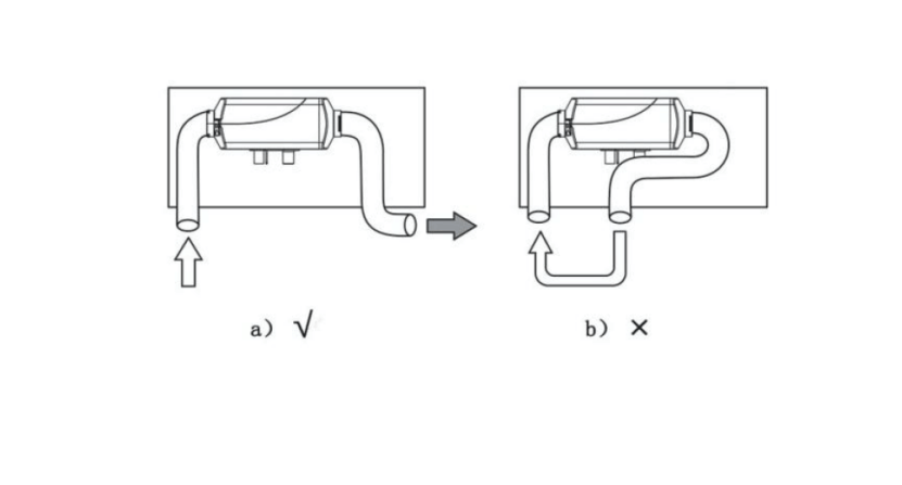
Both the air inlet tube the exhaust tube should come outwards and downwards from the heater otherwise a ï 4 mm
hole shall be prepared at the bottom of the tube for discharge of condensation water. If the tube need curve, the radius can not be smaller than 50 mm. Also, the sum of all curve angles for each tube shall not exceed 270 N.
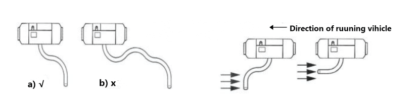
The opening of the tubes should not be opposite to the direction of the running vehicle.
The tube openings should not be blocked by slurry, rain and snow or other dirt. The exhaust tube should be installed in far distance from the plastic parts or other objects with poor thermal resistance of the vehicle body. The exhaust tube should be properly fixed. The exhaust vent should be downwards, perpendicular to road surface with angle of 90£ ¤ 10£. To ensure such an angle, the fixing clip for the exhaust tube should be within 150 mm from the tube end.
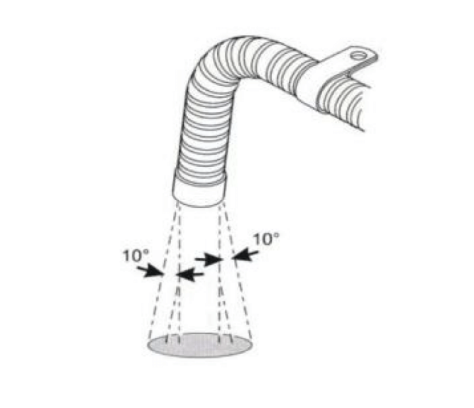
Warning: Violation against the above requirements may cause fire.
If the section of the exhaust tube inside the vehicle may be touched by passenger, a protective cover has to be installed to prevent human contact and scald.
Operation and Control
After the installation, the heater shall be turned on repeatedly for a few times to make the fuel tube full-filled, so as to avoid staring failure due to lacking fuel.
Controller
Rotary Knob Panel Instructions
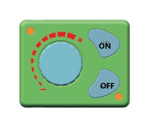
Introduction of keys:
ON →Startup
ОFF → Shutdown
Rotary knob → temperature adjustment and wind speed control
Lighting instructions:
Considering that there is lighting below the ON/OFF-key, the operators will find out the rotary knob easily under the dark environment. The lighting on the outside of rotary knob will off show the temperature value and failure state.
Key function introduction
ON→Please press the ON Key gently when the working voltage has satisfied the related conditions
OFF→Please press the OFF-key gently when the machine is under the working state
Rotary knob →The temperature will rise when the rotary knob is rotated clockwise, at this moment, the red indicators will be increased on the outside or the rotary knob.
→The temperature will down when the rotary knob is rotated anti-clockwise, at this moment. The red indicators will be reduced on the outside of the rotary knob.
Fuel filling by hands
Please rotate the rotary knob clockwise under the OFF state until the red indicators are on, then. Please press the OFF button for more than 3 seconds. At this moment, the manual oil pumping will be started. Please press the OFF seconds.
Tips:
1) The fuel pipe should be 1.5 meter – 2 meters.
2) The voltage would be better, if 11. 5 V- 12.8 V.
Installing picture:

Maintenance
During the running of heater, it tests and checks the operating state and fault in the whole course, and the controller shows fault codes on the LCD/LED constantly.
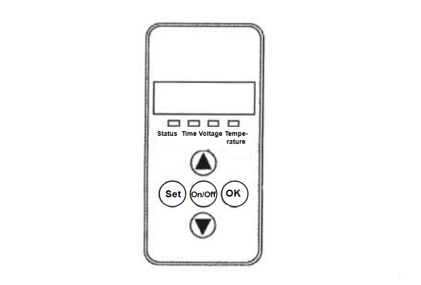
12V-24V Common Digital Panel Operation Instruction
- Indicators
Status→Permanently on upon startup, blinking upon the initialization of shutdown, off upon the completion of shutdown.
Time→Permanently on when displaying the time or setting the timed startup or shutdown, and off under other statuses.
Voltage→Permanently on when displaying voltage or setting the parameters in relation to voltage, and off under other statuses.
Temperature→Permanently on when displaying the ambient temperature or setting the operating temperature, and off under other statuses. - Key Function
▲→Under the setting status, press it to raise the parameter to be set; under the non-setting status, press it to raise the operating temperature to be set.
Set→Enter the setting status to adjust parameters and change the machine’s operating status.
On/Off→Promptly press it to start up the machine, and the status indicator becomes permanently on; press and hold the key for 2 sec to shut down the machine, and the status indicator becomes blinking.
OK→Under the setting status, press it to confirm the current setting value and proceed to the next parameter to be set; under the non-setting status, press it to view the machine’s status.
▼→Under the setting status, press it to reduce the parameter to be set; under the non-setting status, press it to reduce the operating temperature to be set.
FAQs
Q1: How long does it take to complete the VEVOR Diesel Heater Installation?
A: The installation time varies based on experience, but our clear manual ensures a swift process, typically taking a few hours.
Q2: Can I install the VEVOR Diesel Heater in my RV or camper?
A: Absolutely! VEVOR heaters are versatile, suitable for various spaces, including RVs and campers, providing efficient heating on the go
Q3: Is professional assistance required for Fuel Pump Installation?
A: While our manual simplifies the process, seeking professional help ensures optimal performance and safety during Fuel Pump Installation
Q4: What maintenance is required after the Main Heater Installation?
A: Regular cleaning and checking for wear ensure longevity. Refer to our manual for detailed maintenance guidelines post-installation.
Q5: Are VEVOR Diesel Heaters energy-efficient?
A: Yes, VEVOR heaters are designed for efficiency, minimizing energy consumption while delivering powerful heating results.
Q6: Can I use alternative fuels with VEVOR Diesel Heaters?
A: We recommend using standard diesel for optimal performance, as alternative fuels may affect efficiency and longevity.
Q7: How does VEVOR ensure safety during Fuel Supply System installation?
A: Safety is paramount. Follow our manual’s guidelines, including proper ventilation and adherence to safety protocols, for a secure Fuel Supply System installation.
Final Words
In closing, VEVOR diesel heater manual for installation is your gateway to optimal warmth and efficiency. From the detailed guidance on Main Heater Installation to the intricacies of Fuel Filter setup, our manual is a comprehensive roadmap. At VEVOR, we take pride in delivering not just heaters but solutions that redefine comfort. As you embark on this installation journey, trust in the reliability of VEVOR products, meticulously crafted for seamless integration. Make every space cozy with our innovative heating solutions. Elevate your surroundings, enhance your comfort – VEVOR is your trusted partner in warmth. Experience the difference, and let VEVOR heaters transform your environment effortlessly, trust VEVOR for warmth that stands the test of time.


Could you please post a version of the PDF that is readable. It is impossible to read many of the numbers in the images. In my case the heater is going to be a tight fit. The document shows minimum clearances, but they are unreadable.
Thank you for your message. Based on your feedback, I have re-uploaded the DOCX version of the manual for you to download and read.
please, please hire an english speaker to put your english air heater manual in proper order. Its a horrible mistranslated mishmash of irrelevant and dangerous information. Your manual states that vevor will not be responsible for damage if the installation instructions are not followed. The instructions are so terrible they can not be followed. You would lose a lawsuit. Your products are good and very reasonably priced but i think if you spent a little more time on customer support it would mean greater success.
good luck
stalsis.p
Thank you for your kind suggestion, I will feedback relevant issues to the product manager. Thank you for your support of VEVOR products.
Bonjour, pourriez vous faire un point sur les codes erreur SVP avec si possible des solutions. Exemple je viens de recevoir mon VEVOR et il ne démarre pas ERROR 06 (manuel en Anglais et les tuto du Net en Anglais également)
D’avance merci
ERROR 06 signifie un défaut moteur, vous pouvez vérifier la polarité de l’aimant et la position du capteur Hall.
J’utilise le traducteur Google pour traduire les phrases en français, j’espère que cela pourra vous aider.