
We are delighted that you have chosen VEVOR’s products and are confident that you will appreciate the convenience they bring, as well as the satisfaction of promoting the “low carbon and environmental protection” policy.
Please make sure to read the VEVOR Wind Turbine Manual carefully before installing the products.
Table of contents
- Part 1. Safety Warning and Attention
- Part 2. Product Description
- Part 3. Tower and Accessories Production
- Part 4. The Wind Turbine Installation Steps
- Part 5. The Transmission Line Connection With C urrent Collectors
- Part 6. Maintenance and Precautions
- Part 7.Paking List
- Part 8. Quality Guarantee
- Conclusion
Part 1. Safety Warning and Attention
Attention: For correct installation and use of this equipment, please read carefully the safety warning and attention and strictly follow the instructions.
Basic requirements:
● Do not disassemble the equipment by yourself. Please contact the specified
maintenance department when the equipment is out of order.
● Without authority, no company or individual is allowed to change the equipment structure, safety, and performance design.
● Please obey local laws and regulations when using this product
Assembly Requirements:
1. Before the assembly of the wind generator or in the process of maintenance, please be sure to read the user’s manual first.
2. Please don’t install the wind turbines on rainy days or when the wind scale is at Level 3 or above.
3. After opening the package, it is advised to short-circuit the three leads of the wind turbines the exposed copper parts should be screwed together).
4. Before the installation of the wind turbine, lightning grounding must be prepared. You can arrange the facilities according to national standards, or you may arrange them according to the local environment and soil condition.
5.When assembling the Wind turbine, All the parts should be fastened with fasteners specified in Table.
Table 1
| Serial# | Fasteners | spec | Quantity | tighteningtorque (N*M) | remarks | Executive standard |
| 1 | Flange bolts | M12*55 | 4 | galvanized | ||
| 2 | Flat washer | D12.2 | 8 | galvanized | ||
| 3 | Spring washer | D12.2 | 4 | galvanized | ||
4 | tightening torque (N*M) | M12 | 4 | ≥58 | one-timeuse | |
| 5 | Bolts forblades | M6*40 | 6/ 10 | |||
6 | Lock nut for blades | M6 | 6/ 10 | ≥13.6 | one-time use | |
7 | Lock nut on shaft | M16 | 1 | ≥68 | one-time use |
6. Before the connection between the wind turbine flange and the tower flange, please connect the three leads of the wind turbine to the three leads of the tower accordingly.
When using the hinge method, every pair of wires should be no less than 30mm in length and be wrapped with Acetate cloth tape for three layers, then sheathed with a spun glass paint tube. With this method, connect the three pairs of wires (attention: the joint of the wires can’t bear the weight of the tower leads directly, so wires 100mm downward from the joint should be wrapped with adhesive tape and then stuffed into the steel pipe.
After that, wind turbine flange and tower flange can be connected.
7. Before hoisting the wind turbines, the end (which should be connected to the controller) of the tower lead should be cut away the insulating layer for 10mm or so. Then screw the three exposed leads (shot circuit) together.
8. During the installation, it is prohibited to revolve the rotor blades roughly (the ends of wind turbine leads or the tower leads are short-circuited at this moment). Only after all the installation and the examination is finished and the security of the erection crew is guaranteed, it is allowed to dismantle short-circuited leads and then connect with the controller and battery before running.
Attention:
- The battery should be connected to the controller before the wind turbine is connected.
- If the above-stated instructions are not followed when assembling and installing the wind turbines, we are sorry that any problem or failure resulting is not to be covered by warranty.
Part 2. Product Description
1. Low start-up speed; high wind energy utilization; beautiful appearance; low vibration
2. Human-friendly design, easy installation, maintenance and repair.
3. Precise injection molding blades together with the optimized design of aerodynamic contour and structure, the blades have such advantages: high utilization of wind energy which contributes to the annual energy output.
4. The generators, adopting patented permanent magnet rotor alternator, with a special kind of stator design, efficiently decrease resistance torque. Meanwhile, it makes the wind turbines match the generators quite well and increases its reliability.
| Model | 100S | 200S | 300S | 400s |
| Rated power | 100W | 200W | 300W | 400w |
| Maximum power | 130W | 230W | 330W | 430w |
| Nominal voltage | 12/24V | 12/24V | 12/24V | 12/24v |
| Start-up wind speed | 2.0m/s | 2.0m/s | 2.0m/s | 2.0m/s |
| Rated wind speed | 10m/s | 12m/s | 12m/s | 12m/s |
| Survival wind speed | 55m/s | 55m/s | 55m/s | 55m/s |
| Generator net weight | 6.0Kg | 6.5Kg | 6.8Kg | 6.8kg |
| Wind wheeldiameter | 1.2m | 1.3m | 1.3m | 1.3m/s |
| Blades number | 3/5 | |||
| Blade material | Nylon fiber | |||
| generator | Permanent magnet synchronous generator with three-phase alternating current | |||
| Working temperature | Electromagnetic/yaw | |||
| Regulating way | Automatic adjustment of wind angle | |||
| Workingtemperature | -40°C~80°C | |||
| Tower type | Guyed tower | |||
Part 3. Tower and Accessories Production
1. Its flange base is suggested to be installed on an iron barrel-type tower whose OD is 48mm and thickness is 4.5mm.
2. Iron pipe length is suggested to choose based on local wind scales and geographical environment.
3. Tower accessories, including ( 1) The upper tower. (2) The cable group. (3) Tightening line device. (4) Anchor. (5) Line hook. (6) tower base. (7) Anti-tarnish, anticorrosive, coating materials.
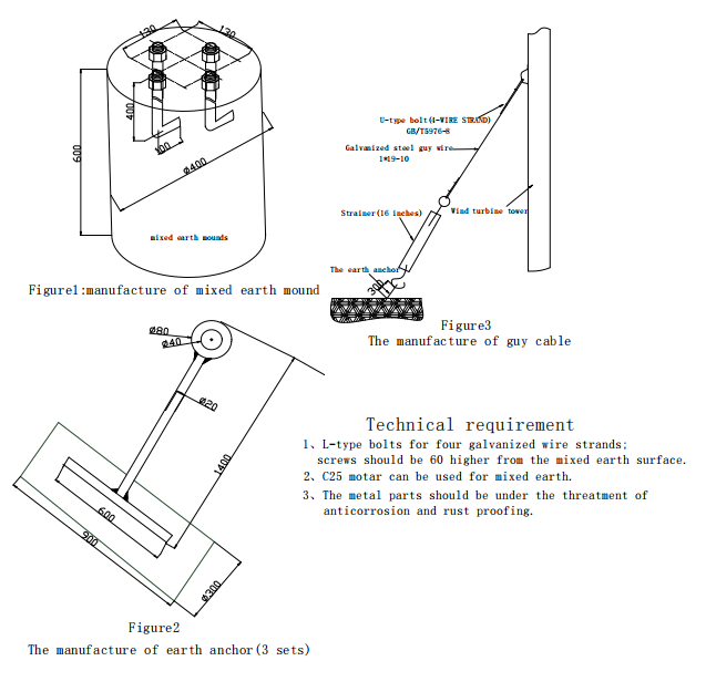
Figure 1: The fabrication of anchor, lasso, and guy cable.
- The making and size of the upper tower is shown in Figure 2. Its requirement: solid welding; no leak at the weld zone; the earth lug must be welded 20cm away from the ground (clearly visible). It will be connected to the lightning grounding device.
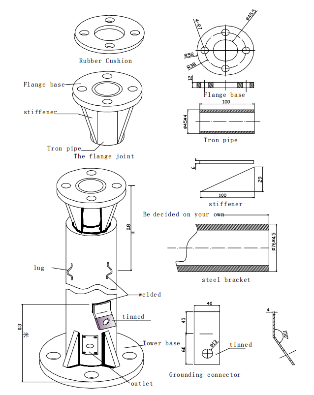
Figure 2. Wind turbine flange connection on the top of the tower
- Please refer to the national standard, the European standard, the American standard, or Figure 1 in this manual to arrange the grounding device.
- The tower and its accessories can be provided individually according to your requirements.
Part 4. The Wind Turbine Installation Steps
Note: It is prohibited to assemble and install wind turbines on rainy days.
1. The insulated current transmission wires: transmission lines are built in the iron pipe tower. The upper end is led out through the center bore of the wind turbine flange, while the bottom end is led out from the pipe opening which is 30cm away from the ground. The section from the opening to the point which is 60cm beneath ground should be protected by iron pipes whose O.D should be 17mm to 21mm. The underground paths of the transmission lines to the controller can made arrayed and covered with iron pipe or a plastic pipe.
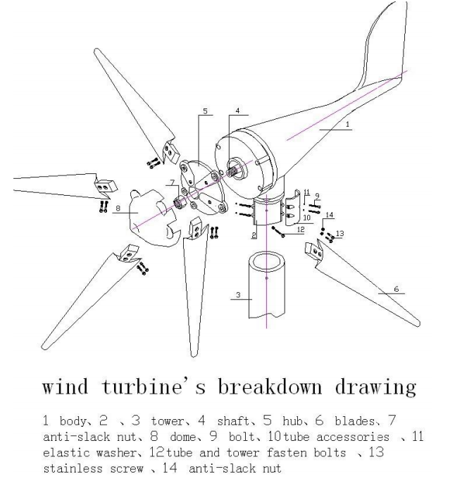
2. The installation sequence of the wind turbines can follow the steps as illustrated in figure3.
2- 1. Place the steel bracket on the ground; block up the flange joint to 1.3m.
2-2. Align the wind turbine flange to the tower flange. Cut away the insulating layer of current transmission wire end ( which is to be connected with the controller) for 10mm, then short circuit the exposed copper wires( screwed together).
2-3. After the flange bolt (9) is mounted with the flat washer ( 10), plug it in the correspondent holes of the wind turbine flange with the bolt’s head up, then through tower flange holes. Set the bolt into the flat washer, the spring washer, and then use a spanner to tighten the nut with the flange bolts. Similarly, plug other bolts, flat washer, and spring washer.
Screw tight all nuts, please refer to Table 2, about the potency dimension needed to tighten them.
3. Align the 2 holes in the blade(6) with 2 holes in the groove of the hub (5), align accurately, then put stainless steel bolt(13) from blade to groove through the holes, then screw lock nut(14)( Attention: lock nut is one-time use, screw tight, do not screw loose, otherwise it will be out of use), installation of other blades follow the same operation, please refer to Table 2 on force dimension of installation.
4. First put the bigger end of the lock nut into a hexagonal hole centered in the hub, then onto the threaded shaft of the generator, press the nut with the left hand while rotating the wheel clockwise with the right. Push the nut, then use the lengthening hex wrench to assist with the right-handed rotation of the wheel. Finally lock the nut (Attention: nut can only push forward, withdrawal is prohibited.) Please refer to Table 2 on Force Dimension of the installation.
5. Clasp fairing (8) with wheel hub (5), align the three notches with blades, and clasp the cone of fairing to get notches to the seam of the wheel hub.
6. The lifting of the wind turbines and tower should be proceeded with the presence of skilled slingers and the security should be guaranteed. The tower’s stance should be executed on the basis of the relevant requirement of permanent construction.
7. After the installation of the tower and lightning protection is finished, use 500V meggar to measure insulating resistance between transmission lines and earth (earth wire can act as ground) in the case of not losing the short-circuited leads of transmission lines, measurement should not be less than 5MΏ, otherwise, the insulating layer may be crushed, damaged or moistened. It should be dealt with immediately.
Figure 3 wind turbine decomposition
Part 5. The Transmission Line Connection With Current Collectors
Note: Avoid heavy rain days for the first commissioning. Priority should be given to the days with gentle breeze or strong wind( wind speed: 5~13m/s).
1. Connect correctly the positive and negative pole of battery to the positive and negative pole of the control inverter (control inverter specially for wind solar hybrid) (solar terminal is for spare use)
2. The load circuit connected to the socket on the back of the control inverter by way of fuses, switches, and plugs.
3. Connect the three current transmission lines of wind turbine to the three terminals on the back of the control inverter. please refer to the control inverter manuals for detailed instruction.
4. Battery selection generally lead-acid battery preferred, 100w-.300W wind turbine 100AH -200AH battery optional, 300W-600W wind generator, 200 ~ 400AH battery optional, the upper and lower limits of charging voltage controlled by the inverter. The wind turbine using the floating charge to battery, the floating current is affected by the battery condition.
5. The controller should be placed in a dry, well-ventilated place, moisture and dust-proofed, inverter shell should be kept grounded and more than 1.5 meters away from the batteries to avoid acid gas pollution.
6. The battery should be put in a dry, ventilated place, cool in summer, and warm in winter. In such environments, the battery can be better maintained.
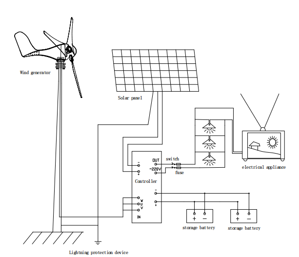
Connection diagram of wind turbine, solar panel & electrical appliance
Part 6. Maintenance and Precautions
- The wind generators often work at poor environments, thus please make sure to check regularly with your sight and hearing; check whether the tower is swaying or whether the cable is loose (using a telescope is also a good idea).
- Timely inspection should be made after a heavy storm. If there is any problem, please put down the tower slowly for maintenance. Regarding the wind turbines for streetlights, there should be an electrician climbing the pole to check if there is any problem when wind turbines have been short-circuited and security protection measures prepared.
- The free maintenance batteries should be kept externally clear.
- Do not disassemble the equipment by yourself. Please contact the sales department when the equipment is out of order.
Part 7.Paking List
Serial# | Item | Quantity | Remarks |
1 | Wind generator | 1 | |
2 | hub | 1 | |
3 | blades | 3/5 | optional |
4 | lock nut on shaft(M16) | 1 | |
5 | bolt for blades(M6*40) | 6/ 10 | optional |
6 | lock nut for blades(M6) | 6/ 10 | optional |
7 | flange bolt(M12*55) | 4 | |
8 | nut(M12) | 4 | |
9 | flat washer | 8 | |
10 | spring washer | 4 | |
11 | bolt for blades(M6*40) | 1 | optional |
12 | lock nut for blades(M6) | 2 | optional |
13 | L spanner | 1 | optional |
14 | hex wrench | 1 | optional |
15 | Controller/inverter | 1 | optional |
16 | tower | 1 | optional |
Part 8. Quality Guarantee
The company guarantees customers that the generator is of excellent quality, its function is good, the body is complete, rigorously checked before delivery
We provide 1 year’s warranty for the wind generator and 1 year for the controller since the date of sale, damages occurred in the following situation: dismantle optionally by yourself or seriously violate operation (not according to instructions use) are not covered by warranty.
ahe documents are as a product warranty certificate, please keep it properly.
User information table:
| Sales company: | Purchase company: |
| Purchase time: | Contact person: |
| SBBH: | Contact: |
| Model: | Zip-code: |
Maintenance records:
| Date | Maintenance species | Summary | SMT rework |
Conclusion
In conclusion, the VEVOR Wind Turbine Manual is a comprehensive and useful guide for anyone looking to install, operate, and maintain a VEVOR wind turbine.
With safety guidelines, product descriptions, and installation steps, this comprehensive manual provides everything you need to know to ensure the safe and efficient operation of your VEVOR wind turbine. We hope that you find this manual helpful and informative as you begin to enjoy the benefits of renewable energy and contribute to a cleaner, more sustainable future.


