
If you’re looking to learn how to use a VEVOR welder or simply need to refresh your knowledge on the safety precautions and professional techniques involved, the VEVOR Welder Manual is an invaluable resource.
In this user’s guide, we will explore the safety precautions and professional welding techniques necessary to ensure your success in welding. Additionally, we will provide you with a PDF version of the manual, making it easy for you to access and reference the information you need. So, let’s get started!

This is the original instruction, please read all manual instructions carefully before operating. VEVOR reserves clear interpretation of our user manual. The appearance of the product shall be subject to the product you received. Please forgive us that we won’t inform you again if there are any technology or software updates on our product.
Table of contents
DECLARATION OF CONFORMITY
The company solemnly promises:
The products sold by our company are guaranteed for one year from the date of purchase.
Please read and understand this manual carefully before the installation and operation of this machine.
- The contents of this manual may be revised without prior notice.
- There may be some inaccuracies in this manual, though it has been carefully examined.
If so, please consult us.
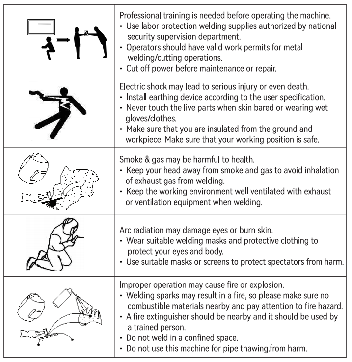
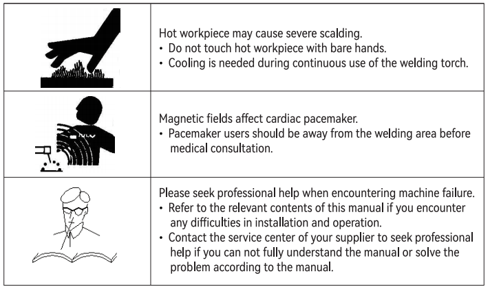
SAFETY
Welding is dangerous and may cause damage to you and others, so take good protection when welding.
For details, please refer to the manufacturer’s safety guidelines for accident prevention.
BRIEF INTRODUCTION OF THE PRINCIPLE
The argon arc welding series is an inverter welding machine that is manufactured with advanced inverter technology. It is a more mature and stable product series.
It uses pulse width modulation technology (PWM) and high-power switching device IGBT to rectify the 50Hz/60Hz power frequency into direct current, and then invert it to high frequency (the frequency can reach above 100KHz) and then step-down rectification. Through the pulse width modulation technology (PWM) output, it can be used as a high-power DC power supply for welding. Due to the switching power supply inverter technology, the weight and volume of the welding machine are greatly reduced, and the conversion efficiency of the whole machine is increased by more than 30%.
When used as manual arc welding, the welder has constant current characteristics and is arc thrust control.
That is, it has a constant current characteristic under normal arc voltage. So the welding current does not change with the arc length to ensure stable welding.
When the arc length is too short and the arc voltage is too low, the current can increase with the decrease of the arc voltage. In order to promote the automatic recovery of the arc length (the so-called arc thrust), the thrust is independently adjustable. When the arc voltage is too small to maintain the arc, the external characteristic changes to a steep drop characteristic to avoid excessive current caused by a short circuit.
The external characteristic of argon arc welding is constant current, so the welding current does not change with the arc length, and the current is very stable.
INSTALLATION
When using a longer output cable, to reduce the voltage drop, it is recommended to use a cable with a larger cross-section. If the welding torch cable is too long, its internal resistance will reduce the output voltage of the equipment, which may have a greater impact on the welding machine’s performance.
The performance of the high-frequency arc is weakened or the system can not work normally. So we suggest that you use the recommended length of cable.
CONNECT WIRING
1. Connection of input cable
• Each TIG welding machine is equipped with a power supply cable. It is used to connect to a power supply of the required voltage input.
• The power supply cable should be well connected to the power switch or the cable connector to avoid possible oxidization.
• Use a multi-meter to check whether the voltage changes within the given range.
2. Connection of output cable (Pure) Argon arc welding (TIG)
• Connection of the argon arc welding torch. Install the gas-electric integrated connector of the welding torch to the corresponding interface on the welding machine panel, and tighten it by turning it clockwise.
• Install the aviation plug to the corresponding interface on the welding machine panel, and tighten it by turning it clockwise.
• Insert the quick plug of the cycle cable into the quick socket with the polarity”+” on the welding machine panel, and tighten it by turning clockwise. Then clamp the workpiece with the ground wire.
3. Connect to the gas
Connect the argon gas pipe tightly with the copper nozzle at the back of the machine. The air supply path should include a gas cylinder, an argon decompression flow meter and a trachea. The connecting part of the trachea should be fastened with hose clamps or other objects to prevent leakage and air ingress. These operations will affect the protection effect of the solder joints.
Use a wire with a conductive cross-sectional area of not less than 4mm’ to ground the chassis. The method is to connect a wire to the ground from the ground screw on the back of the welder to prevent static electricity or leakage.
4. MMA and TIG function
Connect as above during argon welding (TIG). When MMA welding, pay attention to the following.
• Each welding machine is equipped with a pair of quick plugs. Connect the electrode holder cable to the – quick plug, and the earth clamp cable to the “+” quick plug. Pay attention to tighten them with an inner hexagonal wrench. Make the secondary cable (holder wire and earth wire) in good contact with the quick plug.
Some welders neglected this and burned the quick plug.
• After inserting the quick plug into the quick socket, tighten it to ensure good contact. Otherwise, when the working current is high, the plug and socket will be burnt out after long-time work.
5. function
• Connect the cleaning gun correctly. Install the connector of the cleaning gun to the corresponding gun interface on the welding machine panel, and tighten it by turning it clockwise.
• Insert the quick plug of the earth cable into the quick socket with the polarity of”+” on the welding machine panel, and tighten it by turning clockwise. Clamp the workpiece with the earth clamp at the other end.
Serious attention should be paid to the electrode of the wire. Generally, DC welding equipment has two connection modes:
• Positive connection: connect electrode holder to “-“, while connect work piece to “+”;
• Negative connection: connect work piece to “-“, while connect electrode holder to “+”.
OPERATION
Main Switch
• Turn on the power switch on the rear panel and set the power switch to the “ON” position. At this time, the digital display lights up and the fan inside the machine starts to rotate.
Select “TIG”/”MMA” /”CLEAN” mode via the select button.
The select switch can realize the conversion of TIG and MMA.
1. TIG welding operation
• Press the button to turn the argon arc welding (TIG) light on.
• Open the valve of the argon cylinder and adjust the flow meter to the required flow rate.
• After pressing the button of the welding torch, the solenoid valve starts to works, and argon gas starts to output.
• Select the welding current according to the thickness of the work piece.
• The distance between the tungsten electrode of the welding torch and the work piece is 2-4 mm. Press the button of the welding torch. After arc ignition, the high-frequency arc-igniting discharge sound in the machine disappears immediately, and it can work at this time.
2. MMA welding operation
• Press the button to turn the MMA welding (MMA) light on.
• Select the welding current according to the thickness of the work piece.
3. Cleaning function operation
• Press the button to turn the clean function (Clean) light on.
• Select the output current according to cleaning needs.
4. O.C Indicator light
When the indicator is on, it means that the device has entered the protection state due to over-temperature.
And over-temperature is caused by overload, over-current or other reasons. When the over-current and overload disappear, the equipment starts to run normally again.
5. Digital display ammeter
The digital display shows the welding current value.
6. Current regulation
For TIG machine with pulses, the spot welding (Spot) and pulse (Pulse) lights go out when the “MMA” or “Clean” state is selected.
Select the output current according to your needs.
7. Current regulation
For TIG machine with pulses, the spot welding (Spot) and pulse (Pulse) lights go out when the “MMA” or “Clean” state is selected.
Select the output current according to your needs.
(2T/4T) Select switch (add this function according to customer requirements)
Select the desired welding mode (2T/4T) in the argon arc welding state. The operation instructions are as follows:
• Adjust the welding current according to the required welding process. In 2T mode, set the distance between the tungsten electrode of the welding torch and the workpiece to 2-4 mm. Press the torch switch, and the arc will be ignited and you can start welding. Release the hand switch to close arc and stop welding.
• In 4T mode, you can press the torch switch to ignite the arc. When you release the hand switch, welding is continuing. Then press the hand switch again, and the current will slowly drop to the end of the arc.
At this time, release the hand switch, and the welding machine will stop working.
Pre-air time adjustment (Pre Flow)
Pre-air is the time from air supply to arcing. This time can be adjusted between 0 and 1 seconds.
Post-air time adjustment (Post Flow)
Post-air means the time from the arc stop to the air supply cutoff. This time can be adjusted from 1 to 10 seconds.
Select the “Pulse” function
• Select the “TIG” and light on.
• Then select the “Pulse” and light on.
Pulse frequency adjustment “Pulse Frequency” (See the current curve below)
Base current adjustment “Base Amps”
• The base current can only be adjusted in the pulse state. Select the “Pulse”, and select the corresponding base current according to the thickness of the work piece.
Duty cycle adjustment “Peak on time”
• Adjust peak current dwell time.
Front/Back panel
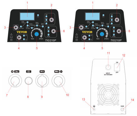
1. Digital Display 8. Connect torch switch
2. TIG, MMA, CLEAN Working Mode 9. Install cutting Torch
3. Pre Flow, welding current, post Flow mode 10. Negative socket
4. 2T/4T Function Button 11. Input power cable
5. Adjustment knob 12. power switch
6. SPOT, DC, PULSE Mode 13. Grounding screw
7. connect the Earth clamp 14. Gas Hose connector
MAIN PARAMETERS
| ITEM | TIG 155 A | TIG 210 A | TIG 210 P |
| Power Voltage (v | AC 110V±10% | AC 110V±10 | AC110V±10 |
| Frequency (HZ | 50/60HZ | 50/60HZ | 50/60HZ |
| Rated Input capacity(KVA) | 3.8 | 7.1 | 7.1 |
| Generator capacity(KVA | 2.3 | 4.2 | 4.2 |
| Rated Input current(A | 38 | 59.2/38.5 | 59. 5/37.5 |
| output current Range (A | 30- 155 | 30-210 | 30-210 |
| output current Range (A | 10- 155 | 10-210 | 10-210 |
| Rated No-load voltage (v | 60 | 60 | 60 |
| Duty cycle ( % ) | 30% | 30% | 30% |
| Insulation class | F | F | F |
| protection class | IP21 | IP21 | IP21 |
| Machine Weight (KG) | 4.9 | 5.4 | 5.4 |
| Machine Dimension (mm) | 370*150*300 | 370*150*300 | 370*150*300 |
| USB Output | / | 5V | / |
| Primary Attachments | 1 . 3.66m QQ150welding gun(includingwe | 1 . WP- 26 weldinggun | 1 . WP- 26 weldingtorch with fineglass mouth ,( L= 4m including we |
| Applicable wire diameter range | <3.2 | <3.2 | <3.2 |
POSSIBLE PROBLEMS
The phenomena listed here may be related to the accessories, gases, environmental factors, and power supply conditions. Please try to improve the environment to avoid this situations.
Black solder joints
Such cases indicate that the solder joints are not effectively protected and are oxidized. You can perform the following checks.
• Confirm that the valve of the argon cylinder is open and the pressure is sufficient. If the pressure in the cylinder is lower than 0.5MPa, refill the cylinder.
• Check whether the argon flow is connected and has sufficient flow. To save gas, different flow rates may be selected for different welding current conditions. But too slow flow rate may result in insufficient shielding gas which can cover the solder joints. No matter how small the current is, we recommend that you do not make the argon flow rate lower than 5L/min.
• The simplest way to check whether there is gas out is to feel the nozzle of the welding torch, so as to check whether the gas path of the welding torch is blocked.
• Poor gas sealing or low gas purity will also cause welding quality problems.
• If there is strong air flow in the environment, it may also lead to the deterioration of welding quality.
• The duty cycle is too low.
It is difficult to start the arc, and it is easy to break the arc:
• Make sure the tungsten electrodes you use are of good quality. The discharge capacity of inferior tungsten electrode may not meet the requirement.
• Unsharpened tungsten electrode is not easy to arc and may cause arc instability.
The current cannot remain stable during the use of the welding machine :
This situation may be related to the following factors:
• The grid voltage variation.
• Serious interference from the power grid or other electrical equipment.
CAUTION
Environment
• The welding operation should be carried out in a relatively dry environment, and the air humidity generally does not exceed 90%.
• The ambient temperature should be between -10°C to 40°C.
• Avoid welding in the sun or rain, and don’t let water or rain seep into the welding machine.
• Avoid welding in dusty or corrosive gas environment.
• Avoid gas shielded welding in strong airflow conditions.
Safety points
The TIG welding machine has been installed with over voltage, over current and over heating protection circuits. When the grid voltage, output current or internal temperature exceeds the set standard, the welding machine will automatically stop working. However, overuse (such as excessive voltage) will still cause damage to the welding machine. Therefore, the following points need to be noted.
Ensure good ventilation
This welding machine is an industrial welding machine. Large working current will be generated during operation, and natural ventilation cannot meet the cooling requirements. Therefore, two fans are installed inside, which can effectively cool the welder and make it work smoothly.
Users should ensure that ventilation areas are not covered or blocked. The distance between the welder and the surrounding objects should not be less than 0.3 meters. Users should always pay attention to maintain good ventilation, because this is conducive to the operation of the welder.
Prohibit overload
The user should remember to observe the maximum allowable load current (relative to the selectable load duration) at any time to keep the welding current not exceeding the maximum allowable load current.
Current overload will significantly shorten the service life of the welding machine, and may even burn out the welding machine.
Prohibit over voltage
The power supply voltage is listed in the “Main Performance Parameters” table. Under normal circumstances, the automatic voltage compensation circuit in the welding machine will keep the welding current within the allowable range. If the power supply voltage exceeds the allowable value, the welding machine will be damaged. The user should be fully aware of this situation and take corresponding preventive measures.
• On the back of each welder there are grounding screws and corresponding grounding marks. Cables with a cross-section larger than 4 mm square should be selected before use. Ground the welder shell to prevent accidents caused by static electricity or leakage.
• If the welder is operating at more than the standard load continuity rate, the welder may suddenly enter a protected state and stop working. It means that the overheating triggers the temperature control switch, so the welding machine stops working. The red indicator on the front panel would light up. In this case, there is no need to unplug because the cooling fan can work to cool the welder. When the red indicator light goes off, the temperature drops to the standard range, and you can restart welding.
MAINTENANCE
• Safety warning: All maintenance and repair work must be carried out with the power completely cut off.
Please make sure that the power plug is removed before open up the machine.
• Regularly check the internal circuit connection of the welding machine to make sure the wiring is correct and the joint is firm (especially the inserted joint or component). If any rust or loose components are found, polish off the rusty layer or oxide film with sandpaper and tighten it again.
• When the machine is energized, keep your hands, hair and tools away from the live parts in the machine, such as internal fans. Avoid being injured or damaged by the machine.
• Regularly blow dust away with dry, dean compressed air. If the welding machine is used in heavy smoke, serious air pollution environment, the welding machine should be dusted every day.
• The compressed air pressure should be at a reasonable level to avoid damaging the small parts in the welder.
• Prevent water or vapor from entering the welding machine. If this happens, dry the inside of the welder.
Subsequently, use a meter to measure the insulation of the welding machine (the insulation between the connecting nodes and the insulation between the connecting points and the casing). Only when there is no abnormal condition can we continue the welding work.
• If the welder is not used for a long time, the welder should be put back into the original packaging box and stored in a dry environment.
TROUBLESHOOTING
Note: The following operations require adequate electrical expertise and comprehensive safety knowledge.
The operator shall have valid qualifications which demonstrate his/her competence and knowledge.
| Phenomena | Solution |
| The power indicator does not light up, the fan does not rotate, and there is no welding output. | 1. The power switch is broken. 2. Confirm whether the power grid connected to the input cable has electricity. 3. Confirm whether there is any open circuit in the input cable. |
| The power switch indicator is on, but the fan does not rotate or rotates several times and stops rotating, and there is no welding output. | 1. The input terminal may be wrongly connected to the 380V power supply, resulting in the start of the over-voltage protection circuit.Replace the 220V power supply and restart the machine. 2. The 220V power supply is unstable (the input line is too thin and too long) or the input line is connected to the grid, resulting in the startup of the over-voltage protection circuit. This phenomenon will disappear in 2-3 minutes by increasing the wire diameter of power grid input or strengthening the input node. When it returns to normal, restart it. 3. Turning the power switch on and off continuously for a short period of time causes the over-voltage protection circuit to start. Turn off the power switch and wait for 2-3 minutes before restarting. 4. The wire between the switch and the power board is loose. Tighten it. 5. The main circuit 24V relay on the power supply board is not closed or damaged.Check the 24V power supply and relay. If the relay is damaged, you can replace it with other breakers of the same model. |
| The power switch indicator is on, but the fan does not rotate or rotates several times and stops rotating, and there is no welding output. | 1. Using a multimeter to measure the positive and negative voltage of VH-07 plug-in from the power supply board to the MOS board is about DC308V. • Whether the silicon bridge plug-in wire is disconnected, and whether the contact is poor. • The large electrolytic capacitors on the power supply board may leak. Replace it. 2. The auxiliary power supply on the MOS board has a green indicator light. If the light is off, the auxiliary power supply is not working. Find the fault point. 3. Check the poor contact of various plug-in wires in the machine. 4. Control circuit problems should be found out in time or contact dealers. 5. The control wire on the welding gun is broken. |
| The abnormal indicator light is not on. There is a high-frequency discharge “rustling” sound, and there is no welding output. | 1. The torch cable is broken. 2. The ground wire is broken or not connected to the welding workpiece. 3. The connection between the positive output terminal or the gas output terminal of the welding torch and the machine is loose. |
| Abnormal indicator light does not light up. There is no rustling sound of high-frequency discharge, and arc welding can be started. | 1. The primary wire of the arc ignition transformer is in poor contact with the power board. Tighten it. 2. It may be that the tip of the TIG welding torch is oxidized or the nozzle is far away from the workpiece. Treatment: remove the oxide film of the nozzle electrode or change the distance between the nozzle and the workpiece to 1 mm. 3. The manual argon welding transfer switch is damaged; replace it. 4. Individual components of the high-frequency arc ignition circuit are damaged; find and replace them. |
| Abnormal indicator light is on, no output. | 1. It may be over current protection. Please shut down the machine and restart it until the abnormal indicator is off. 2. There may be protection from overheating and no need to stop the machine.Wait 2-3 minutes for the machine to return to normal (the pure argon arc welding machine has no overheating protection function). 3. The inverter circuit may be faulty, please unplug the power plug of the main transformer on the MOS board (near the fan VH-07 plug-in) and restart it: • If the abnormal indicator is still on, turn off the machine and then unplug the power supply plug of the high-frequency arc ignition power supply (near the fan VH-03 plug-in) and restart it: a. If the abnormal indicator light is still on, the individual FET on the MOS board is damaged. Find and replace FET of the same type. b. If the abnormal indicator is off, the step-up transformer in the high-frequency arc circuit on the power supply board is broken. Replace it. • If the abnormal indicator is off: a. It may be that the mid-plate transformer is damaged, and the bridge can be used to measure the primary inductance and Q value of the main transformer.L=0.9-1.6mH Q>35 The inductance Q value is very small and should be replaced. b. The secondary rectifier tube of the transformer may be broken down. Find and replace the rectifier tube of the same type. The feedback circuit may be broken. 4. The feedback circuit may be broken. |
| The output current is unstable or no potentiometer control during welding, and the current is sometimes large and sometimes small. | 1. The 1K potentiometer should be replaced if it is damaged. 2. All kinds of poor connection, especially connectors, need to be checked. |
| Manual arc welding has large spatters and it is difficult to burn alkaline electrodes. | 1. If the polarity is wrong, reverse the polarity of the ground wire and the handle wire. |
| The fan does not rotate, the digital meter has no display, and there is no welding output. | 1. Confirm that the air switch is intact or closed. 2. Confirm that the power grid connected to the output cable has electricity. 3. The thermistor (four) on the power supply board is damaged this situation is generally caused by the failure of the DC24V relay or the poor contact of the contacts). 4. The power supply board (bottom board) fails and there is no DC537V voltageoutput. • The silicon bridge is open, and the wire contact of the silicon bridge plug-in is poor. • Part of the power board is burnt. • Check whether the patch cord from the air switch to the power board, and the patch cord from the power board to the MOS board (inverter board) are in good contact. • The auxiliary power supply part of the control board is faulty. |
| The fan rotates, and the abnormal indicator light does not light up. There is no rustling sound of high-frequencydischarge, and the arc cannot be started even if it is rubbed. | 1. Check whether the various patch cords in the machine are in bad contact. 2. If there is a problem with the control circuit, find out the cause in time or contact the dealer. 3. The control wire on the welding torch is broken. |
| The abnormal indicator light is on and no output. | 1. The torch cable is broken. 2. The ground wire is broken or not connected to the welding workpiece. 3. The connection between the positive output terminal or the gas output terminal of the welding torch and the machine is loose. |
| The abnormal indicator light does not light up. There is a rustle of high-frequency discharge, but no welding output. | 1. The primary wire of the arc ignition transformer is in bad contact with the arc ignition plate. Tighten it. 2. It may be that the tip of the TIG welding torch is oxidized, or the nozzle is far away from the workpiece. Treatment: remove the oxide film of the nozzle electrode, or change the distance between the nozzle and the workpiece to 1 mm.and the arc welding can 3. The manual welding argon welding transfer switch is damaged. Replace it. 4. Individual components of the high-frequency arc ignition circuit are damaged.Find and replace them. |
| The abnormal indicator light is on and no output. | 1. It may be over-current protection. Please shut down the machine and restart it after the abnormal indicator is off. 2. It may be overheat protection, and the machine can return to normal without shutting down for 2-3 minutes. 3. The inverter or arc ignition board may be faulty: If it is a dual inverter, unplug the power supply cord plug on one of the inverter boards (near the panel-07 plug-in) and restart it. Then, if the abnormal indicator is not on, the fault is on this inverter, otherwise the fault is on another inverter. Next, both single inverter and dual inverter machines can use the same method to troubleshoot. • If the abnormal indicator is still on, shut down and unplug the power supply on the pilot arc board (near the fan VH-03 plug-in). Restart it: a. If the abnormal indicator light is still on, the individual FET on the MOS board is damaged. Find and replace the FET of the same type. b. If the abnormal indicator is not light, the fault lies in the damage of arc ignition board, the booster or the transformer. Replace it. • Plug in the power supply cord of the faulty inverter, and unplug the power cord of the main transformer. And then restart the machine. a. If the abnormal indicator is off, the fault is in the midplane. The midplane transformer may be damaged, and the bridge can be used to measure primary inductance and Q value of each main transformer. b. The rectifier tube of the middle plate may be damaged individually. Find and replace the rectifier tube of the same type. 4. The feedback circuit may be broken. |
| The welding current is not enough, and the current adjustment is out of control. | 1. The secondary line is too long or too thin, shorten the secondary line as much as possible or increase its cross-sectional area. 2. If there is a remote control device, it may be in the remote control state. 3. It is also possible that the current regulating potentiometer is damaged. |
Conclusion
In conclusion, the VEVOR Welder Manual provides comprehensive information on the safety precautions and professional welding techniques required for successful welding using VEVOR welders. By following the manual, you can ensure your safety, prevent accidents, and achieve high-quality welding results.
The technical data provided in the manual can also help you understand the specifications of each VEVOR welder model, enabling you to choose the right one for your welding needs. Remember to always follow the safety guidelines and take necessary precautions while using a VEVOR welder to ensure a safe and efficient welding experience.


