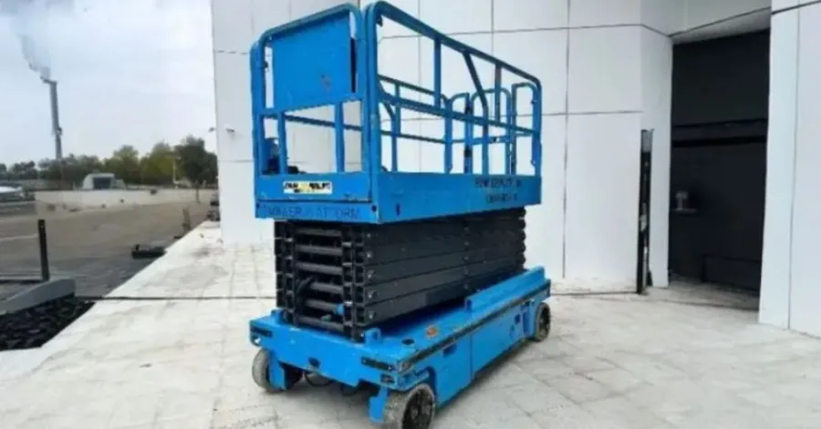
A hydraulic lift is a type of lift that uses pressurized fluid to create force, which is then used to move heavy loads with controlled motion. They are employed in workshops, garages, warehouses, construction sites, and industrial applications. To learn how to build a hydraulic lift system, one should become familiar with the key parts, load limits, frame design, hydraulic lines, and safety precautions. Choosing the right cylinder and pumpe, determining the lifting force, and testing the resulting system can all affect a system’s performance and reliability. This guide will help you understand how a hydraulic lifting system works, the basic process, important parts, capacity calculation, and safety tips.
Innholdsfortegnelse
Components Needed to Build a Hydraulic Lift
Å lære how to build a hydraulic lift system, you need to understand the key components that make up the system. Each has a specific function in generating, regulating, and transmitting hydraulic power. Component compatibility, along with pressure and load ratings, also affects the lift’s safety, performance, and durability.
Anbefalt for ditt prosjekt
Hydraulisk sylinder
Hydraulic pressure is converted to mechanical force by a hydraulic cylinder, which helps the lift move. As the hydraulic oil enters the cylinder, the piston extends the rod and thus lifts the platform. Cylinder size is determined by the lifting force desired, and stroke length determines the distance that the platform will travel. Load capacity is another factor to consider, as it will be necessary that the cylinder is able to safely support the weight that it will be used for. When planning a hydraulic lift system, the factors to think about are the bore diameter, rod diameter, stroke, operating pressure, and mounting arrangement of the cylinder. If sizing is right, the cylinder slides easily and does not overload the system when in use.
hydraulikk~~POS=TRUNC pumpe~~POS=HEADCOMP
Ocuco hydraulisk pumpe pumps fluid from the reservoir into the hydraulic circuit and generates the flow required for lifting. Manual pumps can handle small applications, while powered pumps are generally used when quicker or more frequent lifting is needed. The extension speed of the cylinder and the efficiency of the lift are dependent on the capacity of the pump. Pressure capacity should also be appropriate for the cylinder and anticipated load. If you are considering designing a hydraulic lift system, choose a pumpe that operates at the pressure and flow needed for the entire system. The wrong size pump will cause slow lift, overheating, or poor system performance.
Hydraulisk væskebeholder
The reservoir stores fluid required for lift, gives fluid room to expand, and allows contaminants to settle as well as remove heat from the fluid. It also makes sure that there is a regular supply of hydraulic fluid during the operation of the pump. The reservoir will be sized based on pumpe flow rate, system design, operating cycle, and available space. The tank must be sufficiently large, but not too large. Filtering and ventilation are also very important to maintain fluid quality. With this knowledge of the hydraulic lifting system, it is easy to see why a reservoir is an essential part of the entire hydraulic system and not just a storage tank.
Styreventil
The control valve gives a way for the hydraulic fluid to travel to the different parts of the system and controls the movement of the cylinder. A directional control valve can be used to regulate fluid flow to the cylinder to raise the platform or to lower the platform by regulating fluid flow out of the cylinder. Pressure-control functions keep the operating pressure in an acceptable range and can help to protect the components from excessive pressures. Choose valves to suit the pressure/filling flow rate/valve configuration/cylinder control requirements of the system. The control valve is a crucial component in a hydraulic lift system, controlling the flow of fluid to achieve controlled and predictable lift and lower actions.
Hydrauliske slanger og koblinger
A closed circuit for the fluid to flow within is formed by hydraulic hoses and fittings, which join the pumpe, reservoir, valves, and cylinder. The pressure rating for each hose should be the same or greater than the pressure of the system. Material compatibility is another consideration as the hose and seals need to be compatible with the fluid and conditions used. Fittings should be correctly sized and installed to prevent potential leaks or disconnections. Avoid using a combination of connections or a component with a pressure rating lower than the system when designing a hydraulic lift system. Avoidance of mechanical damage, heat exposure, abrasion, and excessive bending is also achieved by proper routing.
Lifting Platform and Frame
The lifting platform and frame are used for the lifting and transferring of the lifting force of the load. They must be capable of carrying the weight, movement, and forces imposed when operating. While structural strength is crucial, stability and load distribution are also vital. The platform must provide adequate support for the load, and the frame should prevent the load from moving or tilting. When designing for safety, consider the material, size, attachment points, center of gravity, and loading conditions. These structural elements are especially important when considering the question: What are hydraulic lift systems used for? Hydraulic lifts for vehicles, equipment, or materials may significantly differ in the load and stability requirements.
How to Build a Hydraulic Lift System Step by Step
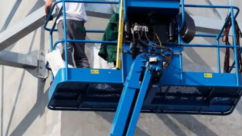
The next step after understanding the key components is to assemble them into a working lifting system. The exact design is dependent on the intended load, lifting height, structure, and hydraulic pressure. A logical assembly sequence helps ensure mechanical and hydraulic components operate correctly together. Below is the main process for building a hydraulic lift system, from calculating the capacity to testing the system.
Bestem nødvendig lastekapasitet
First, calculate the load weight that the hydraulic lift has to lift and maintain. Add the weight of the load to be carried plus the load platform, the frame, and the other moving parts. The total load is used to calculate the cylinder force, hydraulic pressure, and structural strength. Consider where the load will be placed, as uneven distribution can introduce extra forces to the frame and cylinder. During the initial design, also consider the lifting height and required speed. Accurate load calculations will form the basis of the hydraulic lift system design for the application, ensuring the system is not overloaded by the individual components.
Design the Lift Frame
The lift frame is the structure on which the whole system is built, and it will need to carry the lifting forces safely from the cylinder to the platform to the supporting surface. First, lay out the platform dimensions, the positions of support members and pivot points, and the cylinder mounting locations. Think about the load’s distribution on the platform and its motion during the lift. The frame should not allow too much movement or twisting when working under load. As well, cylinder placement is critical, as this angle and where it is attached changes the amount of force needed to lift the cylinder. With a well-thought-out frame, the hydraulic lift system can be smooth and stable in its range of travel.
Install the Hydraulic Cylinder
Once the frame is designed, mount the hydraulic cylinder where planned. The cylinder’s path of travel should be set so it does not bind, side load, or interfere with other components and travels in the path the platform will take. Both ends must be firmly fastened with appropriate hardware for the forces to be applied. Test the cylinder’s extended and retracted operation before connecting hydraulic lines. It is necessary to ensure that there is sufficient clearance for the cylinder rod and other components to be able to move freely during the entire stroke. It’s important because if the cylinder isn’t installed properly, it could put extra pressure on the cylinder, the mounting points, and the frame itself.
Connect the Hydraulic Pump and Reservoir
The circuit for the supply of fluid is the principal part, consisting of the pumpe and reservoir. Use hydraulic lines and fittings suitable for the type of fluid and operating pressure for connecting the reservoir to the pump. Then, when lifting is needed, the pump pumps hydraulic fluid to the control circuit. During assembly, maintain clean openings, hoses, and fittings to avoid contaminating valves, seals, and other hydraulic parts. The pumpe must also be securely installed and housed as per the manufacturer’s requirements. Understanding what a hydraulic lifting system is and how it works helps with assembly because the pumpe must deliver the correct fluid flow and pressure to the cylinder and the rest of the system.
Install the Control Valve and Hydraulic Lines
Wire the control valve between the pumpe, cylinder, and reservoir as per the planned hydraulic circuit. The valve controls fluid direction and allows the cylinder to extend or retract as needed. Connect the pressure and return lines to their correct ports, making sure that hoses are properly routed and supported. Install fittings and hoses that are rated for the correct pressure for the application. Tighten all connections per the component manufacturer’s guidelines, but not so much that you damage the fittings. It is important to have the hydraulic routing correct because if it is not, then the cylinder may not travel correctly or may exhibit unexpected motion as it operates.
Fill the System With Hydraulic Fluid
When all hydraulic components and lines are installed, fill the reservoir with the hydraulic fluid recommended by the pumpe, cylinder, valves, seals, etc. Proper fluid will ensure proper lubrication and system performance. Refill the reservoir via a clean opening and do not allow dirt, moisture, or other contaminants into the system. Note: Don’t overfill the reservoir as fluid levels may fluctuate with the cylinder extension and retraction. The correct equipment fluid level should be in accordance with the equipment manufacturer’s instructions. Proper filling also puts the system into a condition for bleeding to remove any air that could have been introduced into the hydraulic circuit during assembly.
Bleed Air From the Hydraulic System
Air in the hydraulic lines can result in a spongy motion, erratic lift, loud noises, and erratic cylinder movements. Run the system through its intended range of motion prior to applying any large load, following the component manufacturer’s procedures, to help purge any trapped air. Keep an eye on the fluid level in the reservoir as it will vary as the air is vented from the circuit and the cylinder travels. Check for leaks as you do this. Follow the correct bleeding procedure until the system is running smoothly and consistently. The removal of air is a major part of ensuring the hydraulic lift system is ready for controlled operation and also used to detect any problems with the installation prior to its introduction to the intended load.
Test the Hydraulic Lift
The first test should start with no load on the lift, then watch its motion to check for any problems without working load on the structure. Slowly run the cylinder and ensure the platform’s movement in the desired range is smooth. Check during operation for leaks at the frame, cylinder mountings, hoses, fittings, and connections. If the unloaded operation is satisfactory, testing can be conducted in accordance with the rated capacity and manufacturer requirements. Check for any abnormal movements, hydraulic leaks, structural deflection, or any other abnormal behavior. Through proper testing, it is certain that the mechanical and hydraulic parts are functioning in harmony before the lift enters regular service.
How to Calculate Hydraulic Lift Capacity
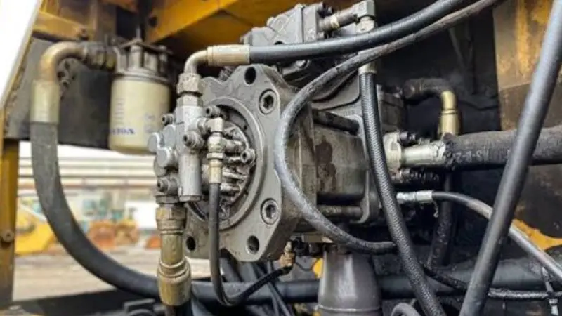
Learning how to build a hydraulic lift system safely and effectively includes calculating the lifting capacity. The force required will vary based on the load, hydraulic pressure, cylinder size, and mechanical arrangement. By knowing these factors, one can pick appropriate components and design a lift to carry the required load without overstressing the hydraulic or structural components.
Calculate the Required Lifting Force
The basic elements of hydraulic lifting force are fluid pressure and the piston area within the cylinder. The basic formula is: Force = Pressure × Piston Area. Cylinder A with a piston area of 10 square inches and a pressure of 1000psi has a theoretical force output of 10 x 1000, or 10,000lbs. But the actual lifting power may be reduced due to friction, mechanical losses, cylinder angle, and other factors. When calculating the force required, consider the weight of the load, platform, frame, and other moving parts. This gives you a solid foundation for choosing the cylinder and pumpe for your hydraulic lift system.
Select the Correct Cylinder Size
The cylinder bore diameter is directly related to the lifting force, as the greater the piston area, the more lifting force is generated under a specific hydraulic pressure. The area of a piston can be calculated from the bore diameter of the cylinder using the formula for the area of a circle. Lifting travel depends on the length of the piston rod, which is limited by the stroke length of the cylinder. Even though the stroke is longer, it does not mean it will have a greater lifting force. The design of a hydraulic lift system should take into account the cylinder bore, stroke, pressure rating, mounting, and travel to suit the application.
Account for Mechanical Advantage
The location and orientation of the hydraulic cylinder may affect the force required to lift a load. A cylinder mounted directly under a platform has a different method of transferring force than when it is mounted with pivot arms, scissor mechanisms, or other linkages. Some designs may allow the cylinder force to be reduced due to mechanical advantage, but the cylinder may have to move further for a desired movement of the platform. The angle of the cylinder in relation to the lift can also vary depending on the lift position, which will impact the amount of force needed during different stages of the lift. Knowing these factors will help you understand how a hydraulic lifting system works and be able to balance the frame, cylinder, and hydraulic pressure more effectively.
Hydraulic Lift Safety Considerations
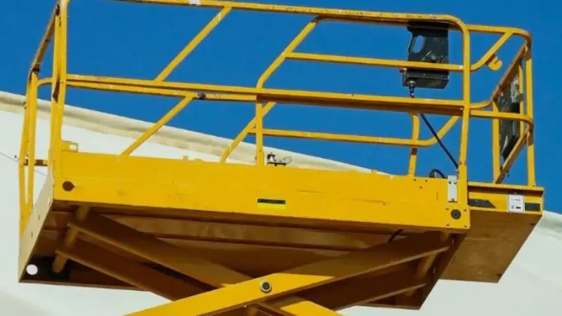
When building a hydraulic lift system, safety is an integral component of doing the job. Carefully select and assemble hydraulic and structural components, as they can generate significant force. To minimize unexpected movement or component failure, use properly rated components and install additional support structures and limit loads.
Choose Components With the Correct Ratings
Choose all components based on the highest load and hydraulic pressure when operating. This will include the cylinder, pumpe, control valve, hoses, fittings, frame, platform, and mounting hardware. Each part should meet application requirements, and parts should be compatible. Structural components must also be sufficiently strong to resist bending and/or deforming under lifting forces. View component ratings in conjunction with each other when designing a hydraulic lift system, not just by a part’s appearance or size.
Use Mechanical Supports for Raised Loads
Never use hydraulic pressure as the only means to secure a raised platform or load. If a hose is damaged or a connection leaks, a valve fails, or hydraulic pressure is lost, unexpected hose movement can occur. When a load needs to be left up, mechanical safety supports, locking mechanisms, or other suitable physical means can provide additional support. These supports should be rated and designed for the load and lifting arrangement they are to be used for. Their use is particularly important when people need to work around or underneath a raised platform. An adequate support system will offer extra security when the hydraulic system is no longer able to maintain the required position.
Stay Within the Lift’s Weight Limit
Do not exceed the rated capacity of the entire lifting system. The actual load should take into account the weight of the material, platform, frame, and other moving parts. Load distribution is also crucial as it can lead to higher stress on the frame, cylinder, and mounting points if they are not evenly distributed. Do not simply presume that a load can be safely lifted by the lift because the hydraulic cylinder has the theoretical power. The pumpe, valves, hoses, fittings, structural frame, and other components should also be able to support the load. Remaining in the lowest rating in which it is found allows for safe and predictable operation.
Inspect the Lift Before Each Use
Check for damage, wear, leaks, or loose connections prior to operation. Inspect hydraulic hoses and fittings for signs of deterioration, such as cracks, abrasion, leaks, or other visual issues. Check for damage or deformities on the cylinder, mounting points, frame, welds, platform, and mechanical supports. Ensure that the platform and supporting structure are stable during the planned movement. If there is any damage or considerable wear, the lift should not be run until the issue is corrected. Proper maintenance, including regular inspections, will help ensure the performance of a hydraulic lift system and can help identify potential issues before they cause equipment failure.
Wrap Up
Building a hydraulic lift requires proper design, appropriate materials, load calculations, and a supporting structure. The cylinder, pumpe, reservoir, control valve, hoses, fittings, frame, and platform should work together within their rating limits. Once you know what the components of a hydraulic lift system are, you can more easily design the entire hydraulic circuit and choose hydraulic components that are compatible. Proper testing and mechanical safety supports are also needed before regular operation. If you are investigating how to design a hydraulic lift system, or to understand more about its applications, you can consider several different factors, including capacity, stability, pressure, and component compatibility, to implement a more reliable and controlled lifting system.
Spørsmål og svar
What are hydraulic lift systems used for?
Hydraulic lift systems can be used at garages, warehouses, construction sites, workshops, and industrial areas to lift vehicles, equipment, materials, platforms, and machinery.
What is the working principle of a hydraulic lifting system?
A piston in a cylinder is extended by a hydraulic pump that pumps pressurized fluid into the cylinder. The mechanical force generated by the piston raises the attached platform or load.
What are parts of a hydraulic lift system?
These include a hydraulic cylinder, hydraulic pump, hydraulic fluid reservoir, hydraulic control valve, hoses, fittings, lifting platform/frame, and appropriate mechanical safety support system.
What is the cost of a hydraulic lift system?
Cost depends on the lifting capacity, sizes of the cylinders, the type of pump, the frame design, materials, controls, and the application. Compared to industrial lifting equipment, small systems tend to be less expensive.