
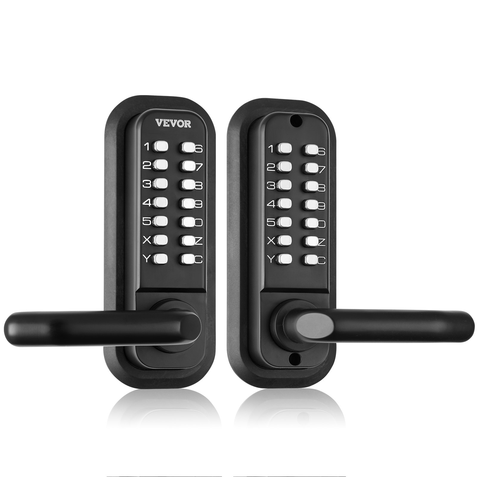
Unlock the ultimate convenience and security with the VEVOR Mechanical Keyless Entry Door Lock. This comprehensive product manual is your go-to guide for mastering the 14 14-digit keypad Double-sided Embedded Outdoor Gate Door lock set. Crafted from waterproof zinc alloy, this robust lock is designed to withstand the elements while providing top-notch security for your yard, garden, or garage.
Our detailed manual covers every lock aspect, from initial setup and installation to troubleshooting and optimization tips. Whether you’re a first-time user or a seasoned pro, you’ll find easy-to-follow instructions and insightful diagrams that make the process a breeze. Discover how to customize the lock codes, maintain the lock’s performance, and ensure long-term durability.
The VEVOR Mechanical Keyless Entry Door Lock manual is designed for ease of use. It will help you optimize your security setup quickly and efficiently. Download now to unlock knowledge and fully control your outdoor security.
VEVOR Keyless Entry Door Lock User Manual
MODELS
- OL-209D2-BY-B-01
- OL-209S2-BY-C-01
WARNING
Read this material before using this product. Failure to do so can result in serious injury.
Keyless Entry Door Lock Assembly precautions
- Assemble only according to these instructions. Improper assembly can create hazards.
- Wear ANSI-approved safety goggles and heavy-duty work gloves during assembly.
- Keep the assembly area clean and well-lit.
- Keep bystanders out of the area during assembly.
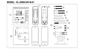
- Front Panel × 1
- Back Panel × 1
- Instruction × 1
- Door Striker Plate*1 set
- Widen protective rubber mat (160x65mm) × 2 pieces
- Screws M4x40mm × 2pcs
- Screws M4x50mm × 2pcs
- Mounting spindle (square root) 55mm × 1pc
- Mounting spindle (square root) 63mm × 1pc
- Mounting spindle (square root) 71mm × 1pc
- Mounting spindle (square root) 79mm × 1pc
- Hollow stud (M5xM4x40mm) × 2
- Spring × 1
- Cross slotted flat head self-tapping screws (wood tooth screws) × 4
- Auxiliary installation drilling sticker × 1

Before installation, please:
- Ensure all parts work correctly.
- Set or Change the password. Passwords are set in different orders and cannot be repeated. A four-digit password is the most secure.
- Ensure that the door lock can be used normally after setting the password. Also, check whether the lock cylinder can be switched freely.
You can insert the lanyards into the square hole of the feed cylinder, turn the lanyards, and the lock tongue can expand normally.
Set/change the password
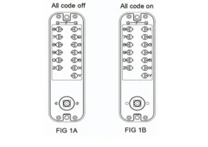
- On the back of the lock body with the number key, you will see the button with the slot, the point of the direction towards the middle. This position is password-free. FIG 1A
- If you want to set a button as a password, please gently push down the button with a one-word screw batch and rotate it 180 degrees so that the point position is opposite to the number. This button is the password. Points outward to “G” FIG 1 B
- To cancel a password, please gently hold the button with the one-word screw batch and rotate 180 degrees so that the dot is facing the middle of the lock body (inward “F”).
- Before installing the door, please remember the password set.
Keyless Entry Door Lock Installation
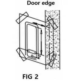
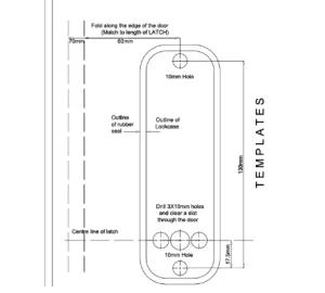
- Correctly position and paste the templates (page 8) to the surface of the inner section at the required height off the ground. Ensure relevant, marked, door-to-door templates are properly aligned with the actual door-to-door. (FIG2)
- The holes marked with a diameter of 10mm are the central shaft holes of the lanvards, and the two holes with a diameter of 7mm are the bolts for digitally locking the spindle through the fastener.
- According to the installation, doors with 6mm diameter holes are marked correctly for the reinforcement pins.
- Drill all marked holes.
Install the Lock Cylinder
- A door marked with a center point on the “latch center line”.
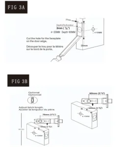
- Drill a hole 25mm in diameter and 80mm in depth at the marked location. (FIG 3A)
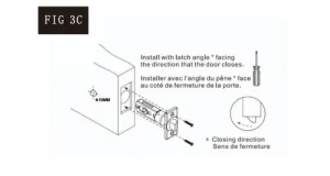
- Put the lock cylinder into the open hole, insert the lanyards into the square hole, and tighten the lock cylinder.
- Drill a small hole 3mm in the mounting hole of the lock cylinder.
- Secure the door with wood national screws to ensure proper positioning.
- Please adjust the size according to the value above the lock cylinder in FIG 3B, when push forward, the size is 60mm, when pull back pull the size is 70mm.
Adjustment handle
- After opening the package, the handle is above the lock body. When adjusting the direction of the handle, it is necessary to confirm the direction of the handle first (left/right open).
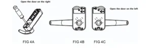
- Loosen the bolt of the lock with a Phillips Screwdriver (FIG.4A) and leave the handle from the lock body.
- Adjust the handle to the desired direction of the door (left/right open) (FIG.4B/C) and then lock the bolts.
- Insert the lanyards into the lanyards hole and turn the stem so that the triangular arrow on the lanyards sleeve faces the handle.
Square bar positioning
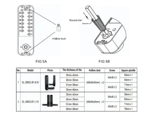
- Please screw the hollow stud into the screw holes of the front panel of the door lock. (FIG 5A)
- According to the thickness of the door, please choose the corresponding size of the drive shaft and mounting screws.
- Bar size default (8×8mm) design, suitable for door thickness of 35 to 65mm. Therefore, if necessary, cut the square bar to fit the thickness of the door.
- Insert one end of the bar with spring into the square hole of the lock bod and insert the other end into the square hole corresponding to the handle of the rear door body. Fixed town see FIG 5B.
Important note: Do not close the door until you have confirmed that the password and lock are working properly.
-
- If necessary, shorten the bolts according to the thickness of the door.
- When shortening the bolts, allow at the least 4/5 threads to screw into the lock box.
- Locate the rubber seal behind the mechanical combination lock, and secure the lock at the neck and bottom with fixing bolts.
- Before final pressing, make sure the town is vertical and test the lock pick function to make sure it is free to move.
- Do not overtighten the locks and seal to avoid damaging the operation of the mechanism.
Doorframe striker plate, box fixed
- Important note: The striker place must be positioned so that the lock lanvards can enter the hole. The safety bolt of the lock lanvards should not enter the striker plate hole.
- In consideration of the above factors, properly place the door frame striker plate.
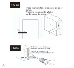
- Once the correct location has been determined mark around the striker plate and the two holes.
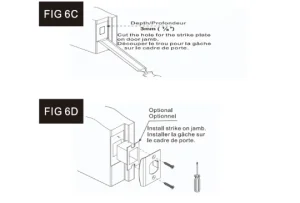
- Remove the striker plate align the second hole of the box with the marked two-hole mark around the box and remove the box.
- Along the open and box size square hole about 24.6mm deep (FIG 6B) can easily put down the box. The front striker plate is flush in the door frame with a 3mm deep square hole (FIG 6C).
Normally open mode setting and cancellation
Firstly, please hold down the handle and Y key, then enter the correct password. When finished entering, please release the handle first and release the Y key, then the normally open mode setting is completed. When need to cancel the normally open mode, hold down the C key and press the handle, then cancellation of normally open mode is completion.
Recommended For Your Project
VEVOR Mechanical Keyless Entry Door Lock, 14 Digit Keypad Manual

Reviews
There are no reviews yet.