

Unlock the full potential of your VEVOR Portable Spot Welder with our comprehensive product manual. Designed for both novice and seasoned welders, this manual provides step-by-step instructions that make setup, troubleshooting, and optimization a breeze.
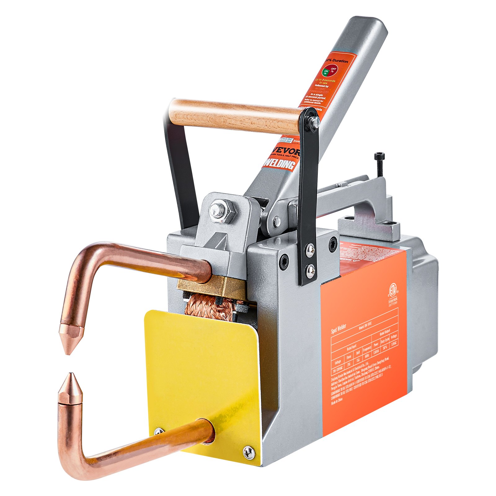
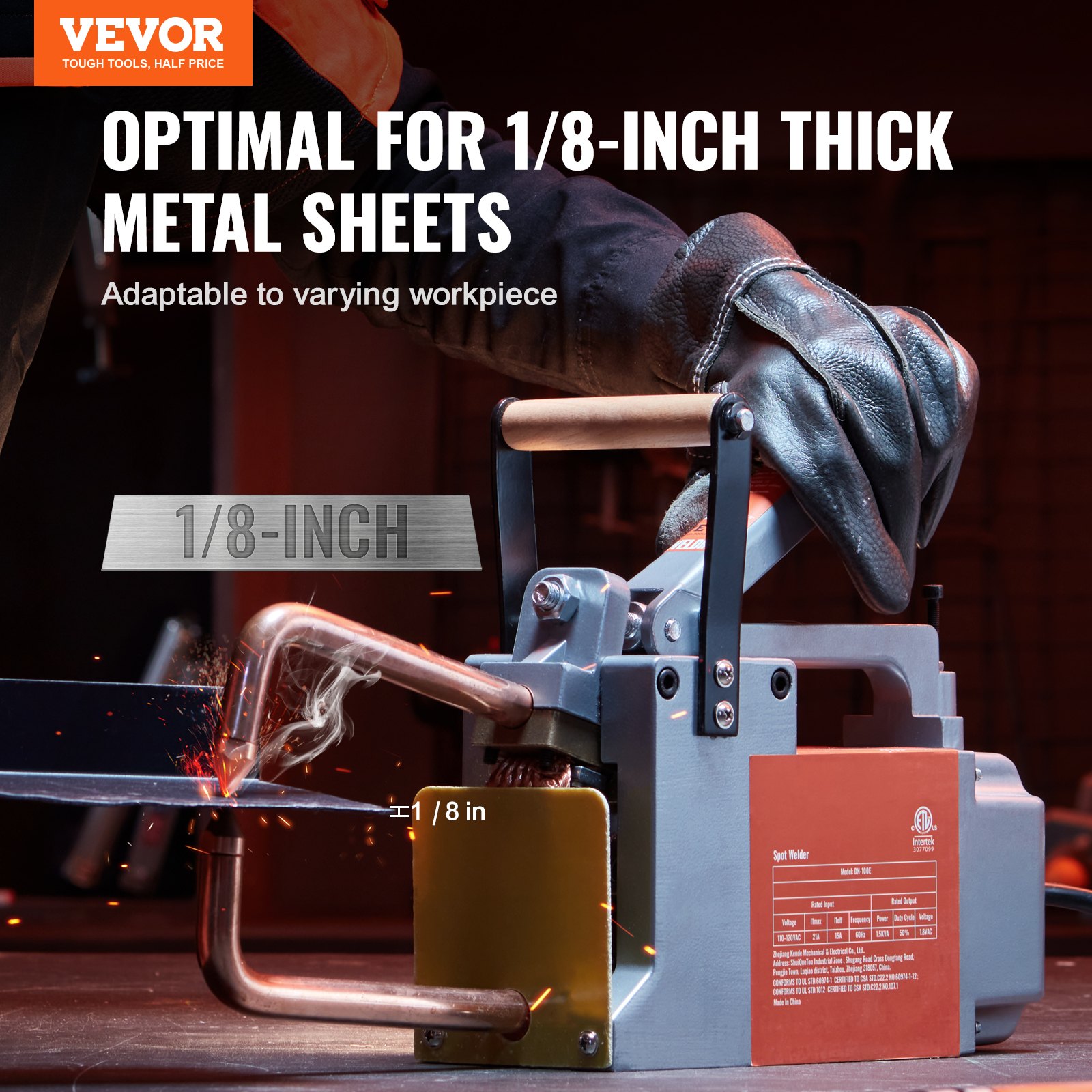
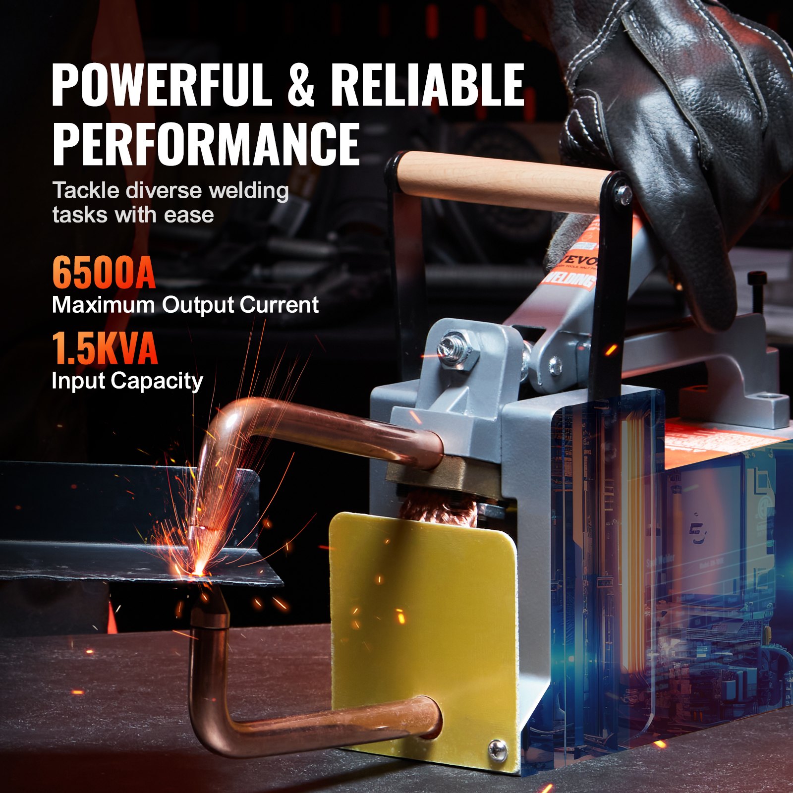
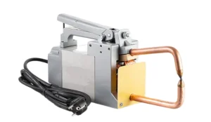
The VEVOR Portable Spot Welder, featuring a 1/8-inch Spot Welder Machine with 1.5 KVA input capacity and a handheld welding tip gun, is ideal for welding metal sheets, including aluminum and carbon steel. This easy-to-follow guide ensures you maximize your spot welder’s performance and longevity.
Whether you’re welding aluminum sheets or carbon steel, our manual covers all aspects of usage, safety precautions, and maintenance tips. Download now to get the most out of your VEVOR Portable Spot Welder and enhance your welding projects with precision and efficiency.
VEVOR PORTABLE SPOT WELDER USER MANUAL
MODEL: DN-100E
SAFETY PRECAUTIONS
- SPOT WELDING can cause fire or explosion.
- Sparks can fly off from the welding arc. The flying sparks, hot workpiece, and hot equipment can cause fires and burns. Accidental contact of the electrode with metal objects can cause sparks, explosions, overheating, or fire. Check and be sure the area is safe before doing any welding.
- Remove all flammables within 35 ft (10.7 m) of the weld. If this is not possible, tightly cover them with approved covers.
- Do not spot weld where flying sparks can strike flammable material.
- Protect yourself and others from flying sparks and hot metal.
- Be alert that welding sparks can easily go through small cracks and openings to adjacent areas.
- Watch for fire, and keep a fire extinguisher nearby.
- Do not weld on closed containers such as tanks, drums, or pipes, unless they are correctly prepared according to AWS F4.1 (see Safety Standards).
- Do not weld where the atmosphere may contain flammable dust, gas, or liquid vapors (such as gasoline).
- Remove any combustibles, such as a butane lighter or matches, from your person before welding.
- After the work is completed, inspect the area to ensure it is free of sparks, glowing embers, and flames.
- Do not exceed the equipment’s rated capacity.
- Use only correct fuses or circuit breakers. Do not oversize or bypass them.
- Follow requirements in OSHA 1910.252 (a) (2) (iv) and NFPA 51 B for hot work and have a fire watcher and extinguisher nearby.
ELECTRIC SHOCK can kill.
- Touching live electrical parts can cause fatal shocks or severe burns. The input power circuit and Portable Spot Welder’s internal circuits are also live when power is on. Incorrectly installed or improperly grounded equipment is a hazard.
- Do not touch live electrical parts.
- Wear dry, hole-free insulating gloves and body protection.
- Additional safety precautions are required when any of the following electrically hazardous conditions are present: in damp locations or while wearing wet clothing; on metal structures such as floors, gratings, or scaffolds; when in cramped positions such as sitting, kneeling, or lying; or when there is a high risk of
unavoidable or accidental contact with the workpiece or ground. For these conditions, see ANSI Z49.1 listed in Safety Standards. And, do not work alone! - Disconnect input power before installing or servicing this equipment. Lockout/tagout input power according to OSHA 29 CFR 1910.147 (see Safety Standards).
- Properly install and ground this equipment according to this manual and national, state, and local codes.
- Always verify the supply ground – check and be sure that the input power cord ground wire is correctly connected to the ground terminal in the disconnect box or that the cord plug is connected to a properly grounded receptacle outlet.
- Attach the grounding conductor first, and double-check connections when making input connections.
- Keep cords dry, free of oil and grease, and protected from hot metal and sparks.
- Frequently inspect the input power cord and ground conductor for damage or bare wiring- replace immediately if damaged, as bare wiring can kill. Check the ground conductor for continuity.
- Turn off all equipment when not in use.
- Check, repair, or replace any leaking hoses or fittings for water-cooled equipment. Do not use any electrical equipment if you are wet or in a damp area.
- Use only well-maintained equipment. Repair or replace damaged parts at once
- Wear a safety harness if working above floor level.
- Keep all panels, covers, and guards securely in place.
FLYING SPARKS can injure.
- Very often, sparks fly off from the joint area.
- Wear an approved face shield or safety goggles with side shields.
- Wear protective garments such as oil-free, flame-resistant leather gloves, a heavy shirt, cuffless trousers, high shoes, and a cap. Synthetic material usually does not provide such protection.
- Protect others nearby by using approved flame-resistant or noncombustible fire curtains or shields. Have all nearby persons wear safety glasses with side shields.
HOT PARTS can burn.
- Do not touch hot parts bare-handed.
- Allow a cooling period before working on the portable spot welder.
- To handle hot parts, use proper tools and/or wear heavy, insulated welding gloves and clothing to prevent burns.
MOVING PARTS can injure.
- The tong tips, tongs, and linkages move during operation.
- Keep away from moving parts.
- Keep away from pinch points.
- Do not put your hands between the tips.
- Keep all guards and panels securely in place.
- OSHA and/or local codes may require additional guarding to suit the application.
- FUMES AND GASES can be hazardous. Welding produces fumes and gases. Breathing these fumes and gases can be dangerous to your health.
- Keep your head out of the fumes. Do not breathe the fumes.
- If inside, ventilate the area and/or use local forced ventilation at the arc to remove welding fumes and gases.
- If ventilation is poor, wear an approved air-supplied respirator.
- Read and understand the Material Safety Data Sheets (MSDSs) and the manufacturer’s instructions for metals, consumables, coatings, cleaners, and degreasers.
- Work in a confined space only if it is well ventilated, or while wearing an air-supplied respirator. Always have a trained watch person nearby. Welding fumes and gases can displace air and lower the oxygen level, causing injury or death. Be sure the breathing air is safe.
- Do not weld in locations near degreasing, cleaning, or spraying operations. The heat and arc rays can react with vapors to form highly toxic and irritating gases.
- Do not weld on coated metals, such as galvanised, lead, or cadmium-plated steel, unless the coating is removed from the weld area, the area is well ventilated, and while wearing an air-supplied respirator. The coatings and any metals containing these elements can give off toxic fumes if welded. 1-3.
Additional Symbols For Installation, Operation, and Maintenance
FIRE OR EXPLOSION hazard.
- Do not install or place the unit on, over, or near combustible surfaces.
- Do not install or operate the unit near flammables.
- Do not overload building wiring -be sure the power supply system is appropriately sized, rated, and protected to handle this unit.
FALLING EQUIPMENT can injure.
- Use equipment of adequate capacity to lift and support the unit.
- When manually lifting heavy parts or equipment, follow the guidelines in the Applications Manual for the Revised NIOSH Lifting Equation (Publication No. 94-110).
- Secure the unit during transport so it cannot tip or fall.
READ INSTRUCTIONS
- Read and follow all labels and the Owner’s Manual carefully before installing, operating, or servicing the unit.
- Read the safety information at the beginning of the manual and in each section.
- Use only genuine replacement parts from the manufacturer.
- Perform maintenance and service according to the Owner’s Manuals, industry standards, and national, state, and local codes.
FLYING METAL or DIRT can injure eyes.
- Wear approved safety glasses with side shields or wear a face shield
- ELECTRIC AND MAGNETIC FIELDS (EMF) can affect Implanted Medical Devices.
- Wearers of Pacemakers and other Implanted Medical Devices should keep away.
- Implanted Medical Device wearers should consult their doctor and the manufacturer before going near arc welding, spot welding, gouging, plasma arc cutting, or induction heating operations.
OVERUSE can cause OVERHEATING.
Allow cooling period; follow rated duty cycle.
Reduce the duty cycle before starting to weld again.
Warnings
- Welding or cutting equipment produces fumes or gases that contain chemicals known to the State of California to cause birth defects and, in some cases, cancer.
- Battery posts, terminals and related accessories contain lead and lead compounds, chemicals known to the State of California to cause cancer, birth defects or other reproductive harm. Wash your hands after handling.
- This Portable Spot Welder contains chemicals, including lead, known to the state of California to cause cancer, birth defects, or other reproductive harm. Wash your hands after use.
For Gasoline Engines:
Engine exhaust contains chemicals known to the State of California to cause cancer, birth defects, or other reproductive harm.
For Diesel Engines:
Diesel engine exhaust and some of its constituents are known to the State of California to cause cancer, birth defects, and other reproductive harm.
EMF Information
Electric current flowing through any conductor causes localised electric and magnetic fields (EMF). Welding current creates an EMF field around the welding circuit and welding equipment. EMF fields may interfere with some medical implants, e.g. pacemakers.
Protective measures for persons wearing medical implants have to be taken. For example, access restrictions for passersby or individual risk assessment for welders. All welders should use the following procedures to minimize exposure to EMF fields from the welding circuit:
- Keep cables close together by twisting or taping them, or using a cable cover.
- Do not place your body between welding cables. Arrange cables to one side and away from the operator.
- Do not coil or drape cables around your body.
- Keep the head and trunk as far away from the equipment in the welding circuit as possible.
- Connect the work clamp to the workpiece as close to the weld.
- Do not work next to, sit on, or lean on the welding power source.
- Do not weld whilst carrying the welding power source or wire feeder. About Implanted Medical Devices:
Implanted Medical Device wearers should consult their doctor and the manufacturer before performing or going near arc welding, spot welding, gouging, plasma arc cutting, or induction heating operations. If cleared by their doctor, following the above procedures is recommended.
Introduction to The Portable Spot Welder
Resistance welding is one of the oldest electric welding processes in the industry today. A combination makes the weld of heat, pressure, and time.
As the name resistance welding implies, the material’s resistance to current flow causes a localised heating in the part. The pressure exerted by the tongs and electrode tips, through which the current flows, holds the parts to be welded in intimate contact before, during, and after the welding current time cycle.
The required amount of time current flows in the joint is determined by material thickness and type, the amount of current flowing, and the cross-sectional area of the welding tip contact surfaces.
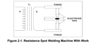
Figure 2-1 illustrates a complete secondary resistance spot welding circuit. The various parts of the Portable Spot Welder are identified for clarity. Some technical parameters are shown on the machine’s nameplate.
SYMBOL AND MEANING ON THE DATA PLATE
U1: Rated AC input voltage of the welding power source
50Hz or 60Hz: Rated frequency of single-phase AC power supply.
I1max: Max. Input current.
I1eff: Max. Effective input current.
X: Rated duty cycle. It is the ratio between the load duration and cycle time.
Note 1: This ratio is between 0~100%.
Note 2: For this standard, one full cycle time is 30 seconds. For example, if the rate is 10%, the loaded time shall be 3 seconds, and the rest time shall be 7 seconds.
If it is used for more than 3 seconds during several successive 10-second periods, it may overheat.
U0: Non-load voltage
It is the open-circuit output voltage of the welding power source.
S1: The rated Input Power, KVA
IP: Protection grade. For example, IP21 approves the welding machine indoors, while IP23 approves it outdoors in the rain.
Class of Insulation: H
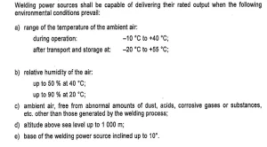
Portable Spot Welder Environmental Conditions
Principle
Resistance welding is accomplished when current is caused to flow through the electrode tips and the separate pieces of metal to be joined. The resistance of the base metal to electrical current flow causes localised heating in the joint, and the weld is made.
The resistance spot weld is unique because the actual weld nugget is formed internally with relation to the surface of the base metal.
Figure 4- 1 shows a resistance spot weld nugget compared to a gas tungsten-arc (TIG) spot weld.
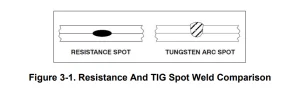
The gas tungsten-arc spot is made from one side only. The resistance spot weld is typically made with electrodes on each side of the workpiece, but it may be made with the workpiece in any position.
The resistance spot weld nugget is formed when the interface of the weld joint is heated due to the resistance of the joint surfaces to electrical current flow. The current must flow, or the weld cannot be made in all cases.
The pressure of the electrode tips on the workpiece holds the part in close and intimate contact during the making of the weld. Remember, however, that resistance spot welding machines are NOT designed as force clamps to pull the workpiece together for welding.
Heat Generation
Ohm’s Law may be modified when watts and heat are considered synonymous. When current is passed through a conductor, the electrical resistance of the conductor to current flow will cause heat to be generated. The basic formula for heat generation may be stated:
H = I2R where H = Heat
I2 = Welding Current SquaredR = Resistance
The secondary portion of a resistance spot welding circuit, including the welded parts, is a series of resistances. The total additive value of this electrical resistance affects the current output of the resistance spot welding machine and the heat generation of the circuit.
The key fact is, although the current value is the same in all parts of the electrical circuit, the resistance values may vary considerably at different points in the circuit. The heat generated is proportional to the resistance at any point in the circuit.
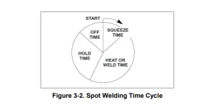
- SQUEEZE TIME -Time between pressure application and weld.
- HEAT OR WELD TIME – Weld time is in cycles.
- HOLD TIME – Time that pressure is maintained after the weld is made.
- OFF TIME – Electrodes separated to permit material movement for the next spot.
The resistance spot welding machines are constructed so that minimum resistance will be apparent in the transformer, flexible cables, tongs, and electrode tips. They are designed to efficiently bring the welding current to the weldment, where the most significant relative resistance is required.
The term “relative” refers to the rest of the welding circuit. There are six major points of resistance in the work area. The areas follows:
- The contact point between the electrode and the top workpiece.
- The top workpiece.
- The interface of the top and bottom workpieces.
- The bottom workpiece.
- The contact point between the bottom workpiece and the electrode.
- Resistance of electrode tips.
The resistances are in series, and each point of resistance will retard current flow. The amount of resistance at point 3, the interface of the workpieces, will depend on the material’s heat transfer capabilities, its electrical resistance, and the combined thickness of the materials at the weld joint.
At this part of the circuit, the nugget of the weld is formed.
The Time Factor
Resistance spot welding depends on the resistance of the base metal and the amount of current flowing to produce the heat necessary to make the spot weld. Another critical factor is time. In most cases, several thousand amperes make the spot weld.
Such amperage values flow through a weld. They quickly create a lot of heat when they flow through a relatively high resistance. To make good resistance spot welds, it is necessary to have close control of the time the current is flowing. Time is the only controllable variable in most single impulse resistance spot welding applications.
Current is often economically impractical to control and unpredictable. Most resistance spot welds are made in very short periods. Since alternating current is commonly used for the welding process, procedures may be based on a 60-cycle time (sixty cycles = 1 second).
Figure 3-2 shows the resistance spot welding time cycle. Previously, the formula for heat generation was used. With the addition of the time element, the formula is completed as follows:
H = I2 RTK where H = Heat
I2 = Current Squared
R = Resistance
T = Time
K = Heat Losses
Control of time is essential. If the time element is too long, the basemetal in the joint may exceed the melting (and possibly the boiling) point of the material. This could cause faulty welds due to gas porosity. There is also the possibility of expulsion of molten metal from the weld joint, which could decrease the cross-section of the joint, weakening the weld.
Shorter weld times also decrease the possibility of excessive heat transfer in the base metal. Distortion of the welded parts is minimised, and the heat-affected zone around the weld nugget is substantially smaller.
Pressure
The effect of pressure on the resistance spot weld should be carefully considered. The primary purpose of pressure is to hold the parts to be welded in intimate contact at the joint interface. This action assures consistent electrical resistance and conductivity at the point of weld. The tongs and electrode tips should NOT be used to pull the workpieces together.
The resistance spot welding machine is not designed as an electrical “C” clamp! The parts to be welded should be in intimate contact BEFORE pressure is applied.
Investigations have shown that high pressures exerted on the weld joint decrease the resistance at the point of contact between the electrode tip and the workpiece surface—the greater the pressure, the lower the resistance factor. Proper pressures, with intimate contact of the electrode tip and the base metal, will tend to conduct heat away from the weld.
Higher currents are necessary with greater pressures, and, conversely, lower pressures require less amperage from the portable spot welding machine. This fact should be carefully noted, particularly when using a heat control with the various portable spot welding machines.
Electrode Tips
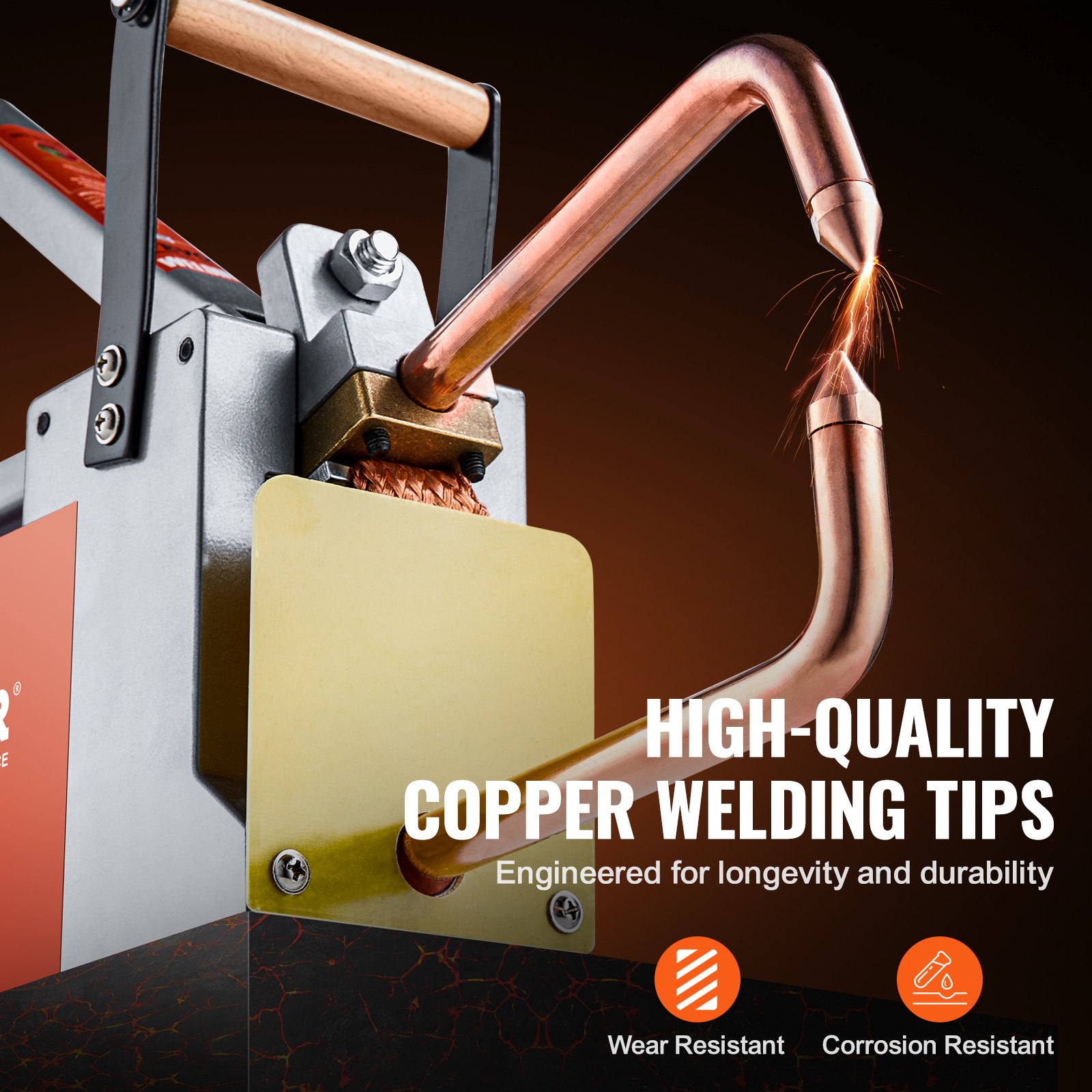
Copper is commonly used for resistance spot welding, tongs, and tips. The purpose of the electrode tips is to conduct the welding current to the workpiece, to be the focal point of the pressure applied to the weld joint, to conduct heat from the work surface, and to maintain their integrity of shape and thermal and electrical conductivity characteristics under working conditions.
Electrode tips are made of copper alloys and other materials. The Resistance Welders Manufacturing Association (RWMA) has classified electrodetips into two groups:
Group A – Copper-based alloys
Group B – Refractory metal tips
The groups are further classified by number. Group A, Class I, II, III, IV, and V are made of copper alloys. Group B, Classes 10, 11, 12, 13, and 14 are refractory alloys.
Group A, Class I electrode tips are the closest in composition to pure copper. The hardness and annealing temperature values increase as the Class Number increases, while the thermal and electrical conductivity decrease.
Group B compositions are sintered mixtures of copper and tungsten, etc., designed for wear resistance and compressive strength at high temperatures.
Group B, Class 10 alloys have about 40 percent of the conductivity of copper, with conductivity decreasing as the number value increases. Group B electrode tips are not commonly used for applications in which portable spot welding machines would be employed.
Practical Uses Of Resistance Spot Welding
SPOT WELDING can be hazardous. Read and follow the Safety Section at the front of this book, the Owner’s Manual, and all labels on the equipment. Resistance spot welding techniques do not require extensive or elaborate safety precautions.
Some common-sense actions can, however, prevent injury to the operator. Anytime work is done in a shop, it is a wise rule to wear safety glasses. Resistance spot welding is no exception to the rule! Very often, metal or oxides are expelled from the joint area. Protection of the face, especially of the eyes, is necessary to prevent serious injury.
Another area of concern is ventilation. This can be a serious problem when resistance spot welding galvanized metals (zinc-coated) or metals with other coatings, such as lead. The fumes from the welding operation have a certain toxicity that will cause illness to the operator. Proper ventilation can reduce the fume concentration in the welding area. As explained in the preceding discussion on the fundamentals of resistance spot welding, there is a definite relationship between time, current, and pressure.
Current and pressure help create the heat in the weld nugget.
If the weld current is too low for the application, the current density is too weak to make the weld. This condition will also overheat the electrodetips, which can cause them to anneal, mushroom, and possibly be contaminated.
Even though time is increased, the amount of heat generated is less than the losses due to radiation and conduction in the workpiece and thermal conduction of the electrodes. With long weld times at low currents, the result is the possibility of overheating the entire base metal area between the electrodes.
This could cause the top and bottom surfaces of the workpiece to burn and possibly embed the electrode tips in the workpiece surfaces. As current density increases, the weld time decreases proportionately. If the current density becomes too high, molten metal may be expelled from the joint’s interface, weakening the weld. The ideal time and current density condition is below the level that causes metal to be expelled.
The heat input cannot be greater than the workpiece’s and the electrode’s total dissipation rate without having metal expelled from the joint. An interesting discovery has recently been made concerning the workpiece’s current flow. Until recently, current was considered to flow in a straight line through the weld joint. This is not necessarily true when multiple thicknesses of material are being welded.
The characteristic is for the current to “fan out,” decreasing the current density at the weld point, the most significant distance from the electrode tips. The illustration (Figure 3-3) shows the resistance spot weld heat zones for several metal thicknesses. We note that the uncontrollable variables (such as interface contamination) are multiplied when resistance spot welding several material thicknesses.
Quality levels will be much lower for “stack” resistance spot welding, which explains why such welding practices are avoided whenever possible. Disregarding the quality factor, it becomes apparent that the number of thicknesses of a material that may be successfully resistant spot welded at a time will depend on the material type and thickness, and the KVA capacity of the portable spot welding machine.
The DN-100 E resistance spot welding machine nameplate shows the KVA rating, duty cycle, and other pertinent information. The catalog literature and the operating manual provide data on the maximum combined material thicknesses each unit can weld.
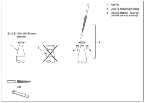
Electrode Tip Size
When you consider that the welding current is permitted to flow into the workpiece through the electrode, it is logical that the electrode tip point size controls the resistance spot weld size. The weld nugget diameter should be slightly less than the diameter of the electrode tip.
If the electrode tip diameter is too small for the application, the weld nugget will be small and weak. If, however, the electrode tip diameter is too large, there is a danger of overheating the base metal and developing voids and gas pockets. In either instance, the appearance and quality of the finished weld would not be acceptable. Determining the electrode tip diameter will require some decisions from the weldment designer.
The resistance factors involved for different materials will certainly affect the determination of the electrode tip diameter. A general formula has been developed for low-carbon steel. It provides electrode tip diameter values that are usable for most applications.
The TIP DIAMETER discussed in this text refers to the electrodetip diameter at the point of contact with the workpiece. It does not refer to the major diameter of the total electrode tip.
Pressure Or Welding Force
The pressure exerted by the tongs and the electrode tips on the workpiece greatly affects the amount of weld current that flows through the joint. The greater the pressure, the higher the welding current value will be within the capacity of the portable spot welding machine. Setting pressure is relatively easy.
Usually, samples to be welded are placed between the electrode tips and checked for adequate pressure to make the weld. If more or less pressure is required, the operating manual for the portable spot welding machine will give explicit directions for making the correct setting.
As part of the setup operation, the tong and electrode tip travel should be adjusted to the minimum required amount to prevent “hammering” the electrode tips and tip holders.
Miscellaneous Data
This section of the text is designed to provide information regarding several variables that occur in some resistance spot welding applications.
Heat Balance
When the materials to be welded are of equal type and thickness, heat balance is not a particular problem. In such cases, the heat balance is automatically correct if the electrode tips are of equal diameter, type, etc. Heat balance may be defined as the conditions of welding in which the fusion zone of the pieces to be joined is subjected to equal heat and pressure.
When the weldment has parts with unequal thermal characteristics, such as copper and steel, a poor weld may result for several reasons. The metals may not alloy properly at the joint’s interface. There may be more localized heating in the steel than in the copper.
The reason would be that copper has low electrical resistance and high thermal transfer characteristics, while steel has high electrical resistance and low thermal transfer characteristics.
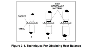
Several methods may be used to obtain the correct heat balance in a weldment of this type.
Figures 3-4 illustrate three possible solutions to the problem.
Figure 3- 4 (a) shows the use of a smaller electrode tip area for the copper side of the joint to equalise the fusion characteristics by varying the current density in the dissimilar materials.
Figure 3-4 (b) shows an electrode tip with high electrical resistance material at the contact point, such as tungsten or molybdenum. The result is to create approximately the same fusion zone in the copper as in the steel.
Figure 3-4 (c) shows a combination of the two methods.
Surface Conditions
All metals develop oxides which can be detrimental to resistancespot welding. Some oxides, particularly those of a refractory nature, are more troublesome than others. In addition, the mill scale found on hot-rolled steels will act as an insulator and prevent good-quality resistance spot welding.
Surfaces to be joined by this process should be clean, free of oxides and chemical compounds, and have a smooth surface.
Materials Data For Resistance Spot Welding
This section of the text will consider methods used for resistance spot welding and some common metals used in fabrication work. It is not intended that all the possible problems that could arise will be answered. This part of the text aims to provide general operational data for use with resistance spot welding machines.
Where applicable, the data provided will be related to specific models and size (KVA) of units. The units listed in this section are not recommended for aluminium or copper alloys.
Mild Steel
Mild or low-carbon steel comprises the most significant percentage of material welded with the resistance spot welding process. All low-carbon steels are readily weldable with the process if proper equipment and procedures are used.
The carbon steels tend to develop hard, brittle welds as the carbon content increases if proper post-heating procedures are not used. Quickquenching of the weld, where the nuggets cool rapidly, increases the probability of hard, brittle microstructure in the weld.
Hot-rolled steel will usually have mill scale on the surface of the metal. This type of material is usually not resistance spot welded with resistance welding machines of the KVA ratings of specifically built units.
Cold rolled steel (CRS) and hot rolled steel, pickled and oiled (HRSP&O), may be resistance spot welded with very little trouble. If the oil concentration is excessive on the sheet metal, it could cause carbon formation at the electrode tips, decreasing their useful life.
Degreasing or wiping is recommended for heavily oiled sheet stock. The resistance spot weld should have shear strength equal to the base metal’s shear strength and should exceed the strength of a rivet or a fusion plug weld of the same cross-sectional area.
Shear strength is usually accepted as the criterion for resistance spot weld specifications, although other methods may be used. A common practice is to “peel” two welded sample strips apart to see if a clean “rivet” is pulled from one piece. If it is, the resistance spot welding condition is considered correct.
With magnetic materials such as mild steel, the current through the weld can vary substantially depending on how much of the magnetic material is within the tongue loop. The tong loop is sometimes called the “throat” of the resistance spot welding machine.
For example, the part to be welded may have the largest amount of the basemetal within the throat of the unit for any one resistance spot weld and almost none of the base metal in the throat for the second spot weld. The current at the weld joint will be less for the first weld.
The reason is the reactance caused by the ferrous material within the arc welding circuit. Resistance spot welding machines are used for low-carbon welding. For best results, they must be used within their rated capacity of total material thickness. They should not be used over the duty cycle since damage to the contactor and transformer may result.
The 30 per cent duty cycle provided for this type of equipment should be adequate for all applications within its rating. The 30 per cent duty cycle is an RWMA standard rating for general-duty resistance welding machines. It is based on 10 seconds, meaning the unit can weld 3 seconds out of 10 seconds.
Low Alloy And Medium Carbon Steels
There are some pertinent differences in resistance spot welding of low-alloy and medium carbon steels as compared to mild or low carbon steels. The resistance factor for the low alloy and medium carbon steels is higher; therefore, the current requirements are slightly lower.
Time and temperature are more critical since these alloys will have greater metallurgical changes. There is certainly more possibility of weld embrittlement than mild steel. Resistance spot welding pressures usually are higher with these materials because of the additional compressive strength inherent in the low-alloy and medium carbon steels.
It is always a good idea to use longer welding times when welding these alloys to retard the cooling rate and permit more ductile welds.
Stainless Steels
The chrome-nickel steel alloys (austenitic) have very high electrical resistance and are readily joined by resistance spot welding. A very important consideration with these materials is rapid cooling through the critical range, 800 to 1400°F.
The rapid quench associated with resistance spot welding is ideal for reducing the possibility of chromium carbide precipitation at the grain boundaries. Of course, the longer the weldment is held at the critical temperatures, the greater the chance of carbide precipitation.
Steels, Dip Coated Or Plated
The overwhelming majority of material in this category is galvanised or zinc-coated steel. Although some galvanised steel is electroplated, dip-coated steel costs less and is in predominant use. The thickness of the zinc coating on dip-coated steel is uneven.
The resistance factor will vary from weld to weld, making it challenging to set conditions for the material in chart form.
It is impossible to maintain the integrity of the galvanised coating when resistance spot welding. The low melting point of the zinc coating, compared to the fusion temperature of the steel sheet, causes the zinc to vaporise. Of course, there must be adequate pressure to force the zinc aside at the weld interface to permit steel-to-steel fusion.
Otherwise, the strength of the resistance spot weld is open to question. Materials are available to repair the external damage to the coating that may have been incurred because of the welding heat. Unfortunately, there is no remedy for the loss of coating material at the weld interfaces.
The vaporisation of the zinc can cause porosity in the weld and a general weakening of the expected shear strength.
▲The VAPORIZED ZINC forms particles shaped like fishhooks upon condensation to solid material. These particles CAN embed themselves in the tissues of THE BODY and irritate. Use forced ventilation or exhaust at the weld area and wear long-sleeved shirts, long pants, protective face shields and coated material when working with this process.
Other coated material, such as terne plate (lead coated) may havevaryingdegrees of toxicity. Adequate ventilation is mandatory when working with these materials. The vaporisation of the coating material tends to foul the electrodetips.
The tips should be cleaned frequently to prevent the alloying of the lower melting materials with the copper tips.
To maintain product quality, the tips may require cleaning and dressing every fourth or fifth weld, although for some galvanised applications, the best welds are made after several spots blacken the tips. Short weld times will increase the possibility of good welds with the least tip fouling.
Aluminum And Aluminum Alloys
Resistance spot welding machines with KVA ratings much greater than 20 KVA are necessary to make sound welds on most aluminium materials and any other high-conductivity type of base metal. Aluminium’s electrical conductivity is high, and the Portable Spot Welder must provide high currents and exact pressures to melt the aluminium and produce a sound weld.
Summary
Resistance spot welding is a technique used for almost all known metals. The actual weld is made at the interface of the parts to be joined. The electrical resistance of the material to be welded causes localised heating at the interfaces of the metals to be joined. Welding procedures for each type of material must be developed for the most satisfactory results.
Shunt currents may flow through a previously made spot weld, taking welding current away from the second spot weld to be made. This will occur if the two spot welds are too close together, and it will happen with
metals.
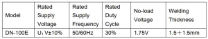
Table 3-1 provides the rating information for a DN-100E resistance spot welding machine. The rating information may differ between the different types of the DN-100E spot welding machine. For example, the rated supply voltage is 230V/120V, the rated supply frequency is 50Hz or 60Hz, the rated duty cycle is 30% or 50%, etc. The rating information depends on the client’s requirements.
Table 3-1. Resistance Spot Welding Machine Specifications of a DN-100E spot welding machine
The following general data is provided to assist the operator in setting up welding procedures when using the resistance spot welding machine. Tong pressure settings should be made ONLY when the primary power cordisdisconnected from the primary power input supply.
Close tongs and measure space between electrode tip contact surfaces.
Measure the thickness of the total weldment.
Adjust tong gap to measurement of Step 2 less 1/2 the thicknessof the thinnest weld number.
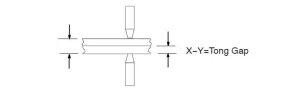
Insert the parts to be welded between the electrode tips and bring tips to welding pressure. There should be a slight deflection of the tongs. This may be measured with a straight edge set on the tong longitudinal axis.
Energize the spot welding machine and make a sample weld.
Test the weld by visual and mechanical means. Check the electrode tip for deformation and contamination (see test procedures).
Adjust tong pressure as required (see Operating Manual for tong adjustment procedures).
Test Procedures
The test procedures outlined are very simple and require a minimumof equipmentto perform.
Visual Test
Observe the deformation and shape of the surface contact points at bothsidesofthe weld. Excessive “dishing” of the surface contact point indicates oneor moreofthe following:
- Excessive tong pressure.
- Weld time too long.
- Misalignment of the electrode tips.
If the resistance spot weld does not have an even, concentric surface appearance,the problem could be misalignment of the electrode tips. Align electrodetipswiththe power off and a typical weld joint between the tip surfaces.
Mechanical Test
Place one end of the resistance spot weld sample in vice jaws. Use mechanical means to force the weld apart. One side of the weld should pull loose from the parent metal with a metal extension from the weld. Check for proper weld diameter.
Portable Spot Welder Maintenance and Troubleshooting
Maintenance
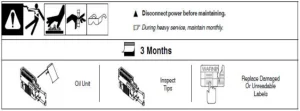
Dressing Tips
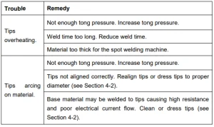
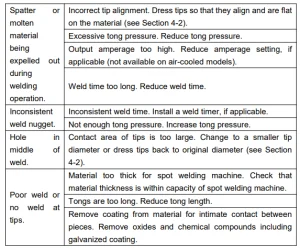
Portable Spot Welder Troubleshooting
Made In China
Recommended For Your Project
VEVOR Portable Spot Welder, 1/8-inch Manual
Reviews
There are no reviews yet.