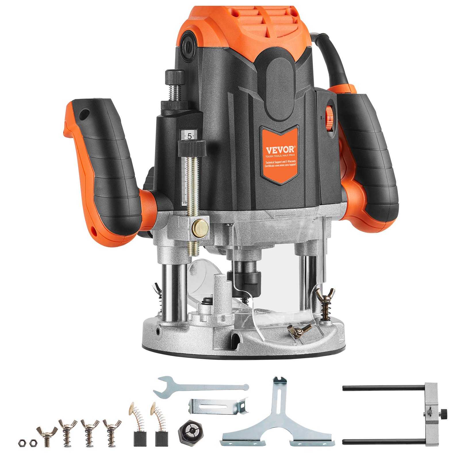


Unlock the full potential of your VEVOR Plunge Router with our comprehensive product manual download. Designed for the 3-1/4 HP, 120V, 12000-23000 RPM Variable Speed Electronic Plunge Base Router, this manual is an indispensable resource for novice and experienced woodworkers.
Inside, you’ll find detailed setup instructions, troubleshooting tips, and optimization techniques to get the most out of your Plunge Woodworking Router Kit. The manual covers everything from the initial assembly and calibration to advanced woodworking techniques, ensuring you consistently achieve professional results.
Whether you’re using the parallel guide, straight guide, or the 1/4″ collet cone set, our manual provides clear, step-by-step guidance to enhance your woodworking projects.
Download now and ensure your VEVOR Plunge Router always performs at its best. This manual is your go-to guide for mastering the VEVOR Plunge Router, perfect for those who value precision and efficiency.
General Safety Rules
Warning! Read all instructions. Failure to follow all instructions listed below may result in electric shock, fire, and/or serious injury. The term “power tool” in all of the warnings listed below refers to your mains-operated (corded) power tool or battery-operated (cordless) power tool.
Save these Instructions
The term “power tool” in the warnings refers to your mains-operated (corded) power tool or battery-operated (cordless) power tool.
Work Area Safety
- Keep the work area clean and well-lit. Cluttered and dark areas invite accidents.
- Do not operate power tools in explosive atmospheres, such as those containing flammable liquids, gases, or dust. Power tools create sparks that may ignite the dust or fumes.
- Keep children and bystanders away while operating a power tool. Distractions can cause you to lose control.
Electrical Safety
- Power tool plugs must match the outlet. Never modify the plug in any way. Do not use adapter plugs with earthed (grounded) power tools. Unmodified plugs and matching outlets will reduce the risk of electric shock.
- Avoid body contact with earthed or grounded surfaces such as pipes, radiators, ranges, and refrigerators. If your body is earthed or grounded, you are at an increased risk of electric shock.
- Do not expose power tools to rain or wet conditions. Water entering a power tool will increase the risk of an electric shock.
- Do not abuse the cord. Never use it for carrying, pulling, or unplugging the power tool. Keep the cord away from heat, oil, sharp edges, or moving parts. Damaged or entangled cords increase the risk of electric shock.
- When operating a power tool outdoors, use an extension cord suitable for outdoor use. Use of a cord suitable for outdoor use reduces the risk of electric shock
Personal Safety
- Stay alert, watch your actions, and use common sense when operating a power tool. Do not use a power tool while you are tired or under the influence of drugs, alcohol, or medication. A moment of inattention while operating power tools may result in serious personal injury.
- Use safety equipment. Always wear eye protection. Safety equipment such as dust masks, non-skid safety shoes, hard hats, or hearing protection used for appropriate conditions will reduce personal injuries.
- To avoid accidental starting, ensure the switch is in the off position before plugging it in. Carrying power tools with your finger on the switch or plugging in power tools with the switch on invites accidents.
- Remove any adjusting key or wrench before turning the power tool on. A wrench or key left attached to a rotating part of the power tool may result in personal injury.
- Do not overreach. Keep proper footing and balance at all times. This enables better control of the power tool in unexpected situations.
- Dress properly. Do not wear loose clothing or jewellery. Keep your hair, clothing, and gloves away from moving parts. Loose clothes, jewellery, or long hair can be caught in moving parts.
- If devices are provided for connecting dust extraction and collection facilities, ensure they are connected and properly used. The use of these devices can reduce dust-related hazards.
Power Tool Use and Care
- Do not force the power tool. Use the correct power tool for your application. The correct power tool will do the job better and safer at the rate for which it was designed.
- Do not use the power tool if the switch does not turn on and off. Any power tool that cannot be controlled with the switch is dangerous and must be repaired.
- Disconnect the plug from the power source and/or the battery pack from the power tool before making any adjustments, changing accessories, or storing power tools. Such preventive safety measures reduce the risk of starting the power tool accidentally.
- Store idle power tools out of the reach of children. Do not allow persons unfamiliar with the power tool or these instructions to operate the power tool. Power tools are dangerous in the hands of untrained users.
- Maintain power tools. Check for misalignment or binding of moving parts, breakage of parts, and any other condition that may affect their operation. If damaged, have the power tool repaired before use. Poorly maintained power tools cause many accidents.
- Keep cutting tools sharp and clean. Properly maintained cutting tools with sharp edges are less likely to bind and are easier to control.
- Use the plunge router, accessories, tool bits, etc., in accordance with these instructions and in the manner intended for the particular type of power tool, taking into account the working conditions and the work to be performed. Using the power tool for operations different from those intended could result in a hazardous situation.
Service
- Have a qualified repair person service your plunge router using only identical replacement parts. This will ensure its safety.
- Follow the instructions for lubricating and changing accessories.
- Keep handles dry, clean, and free from oil and grease.
USE PROPER EXTENSION CORD. Make sure your extension cord is in good condition. When using an extension cord, use one that is heavy enough to carry the current your product will draw. An undersized cord will cause a drop in line voltage, resulting in loss of power and overheating.
Table 1 shows the correct size depending on cord length and nameplate ampere rating. If in doubt, use the next heavier gauge. The smaller the gauge number, the heavier the cord.

Specific Safety Rules
DO NOT let comfort or familiarity with a product (gained from repeated use) replace strict adherence to router safety rules. If you use this tool unsafely or incorrectly, you can suffer serious personal injury.
- Hold power tools by insulating gripping surfaces when operating where the cutting tool may contact hidden wiring or its own cord. Contact with a “live” wire will make exposed metal parts of the tool “live” and shock the operator.
- Use clamps or another practical way to secure and support the workpiece to a stable platform. Holding the work by hand or against your body leaves it unstable and may lead to loss of control.
- Wear hearing protection during extended periods of operation.
- Handle the bits very carefully.
- Check the bit carefully for cracks or damage before operation. Replace cracked or damaged bits immediately.
- Avoid cutting nails. Inspect for and remove all nails from the workpiece before operation.
- Hold the tool firmly with both hands. Keep your hands away from rotating parts.
- Ensure the bit does not contact the workpiece before the switch is turned on.
- Let the tool run for a while before using it on an actual workpiece. Watch for vibration or wobbling that could indicate an improperly installed bit.
- Be careful of the bit’s rotating direction and the feed direction.
- Do not leave the tool running. Operate the tool only when hand-held.
- Always switch off and wait for the bit to come to a complete stop before removing the tool from the workpiece.
- Do not touch the bit immediately after the operation; it may be extremely hot and could burn your skin.
- Do not carelessly smear the tool base with thinner, gasoline, oil, or other similar substances. These may cause cracks in the tool base.
- Please draw attention to the need to use cutters with the correct shank diameter and suitable for the tool’s speed.
- Some materials may contain toxic chemicals. Use caution to prevent dust inhalation and skin contact. Follow the material supplier’s safety data.
- Always use the correct dust mask/respirator for your work material and application.
Save These Instructions
WARNING:
MISUSE or failure to follow the safety rules stated in this instruction manual may cause serious personal injury.
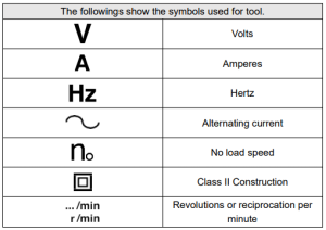
Symbols
Specifications
- Model: 5120
- Ratings: AC-120V 60Hz 15A
- Maximum Power: 3.25HP±10%
- Collet Chuck Capacity: 1/4″ or 1/2″
- Plunge Capacity: 0 – 50mm
- No Load Speed: 12000- 23000 RPM
- Net Weight: 5.5 kg
- Due to our continuing research and development programme, the specifications here are subject to change without notice.
- Note: Specifications may differ from country to country.
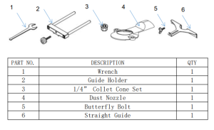
Accessories
Caution
These accessories or attachments are recommended for use with the tool specified in the manual. Using any other accessories or attachments might present a risk of injury to persons. Only use the accessory or attachment for this stated purpose. Ask your local service center if you need more details regarding these accessories.
Functional Description
Caution
- Always be sure that the tool is switched off and unplugged before adjusting or checking function on the tool.
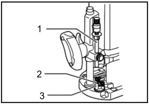
Adjusting the depth of cut
1. Adjusting knob
2. Lock lever
3. Stopper pole
4. Fast-feed button
5. Stopper block
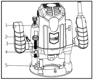
Place the tool on a flat surface. Loosen the lock lever and lower the tool body until the bit just touches the flat surface. Tighten the lock lever to lock the tool body.
Turn the stopper pole setting nut counterclockwise. Lower the stopper pole until it makes contact with the adjusting bolt. Align the depth pointer with the “0” graduation. The depth pointer indicates the depth of cut on the scale.
While pressing the fast-feed button, raise the stopper pole until the desired depth of cut is obtained. Minute depth adjustments can be obtained by turning the adjusting knob (1 mm (3/64″) per turn).
By turning the stopper pole setting nut clockwise, you can fasten the stopper pole firmly.
Now, your predetermined depth of cut can be obtained by loosening the lock lever and then lowering the tool body until the stopper pole makes contact with the adjusting hex bolt of the stopper block
Stopper Block
1. Stopper pole
2. Adjusting bolt
3. Stopper block
The stopper block has three adjusting hex bolts that raise or lower 0.8mm (1/32″) per turn. These adjusting hex bolts allow you to easily obtain three different depths of cut without readjusting the stopper pole.
Adjust the lowest hex bolt to obtain the deepest depth of cut, following the “Adjusting depth of cut” method. Adjust the two remaining hex bolts to obtain shallower depths of cut. The differences in height of these hex bolts are equal to the differences in depths of cut.
To adjust the hex bolts, turn the hex bolts with a screwdriver or wrench.
The stopper block is also convenient for making three passes with progressively deeper bit settings when cutting deep grooves.
Caution
- Since excessive cutting may cause overload of the motor or difficulty in controlling the tool, the depth of cut should not be more than 15mm (19/32″) at a pass when cutting grooves with an 8 mm(5/16″) diameter bit.
- When cutting grooves with a 20 mm (13/16″) diameter bit, the depth of cut should not be more than 5 mm (3/16″) at a pass.
- Make two or three passes with progressively deeper bit settings for extra-deep grooving operations.
Switch Action
Caution
Before plugging in the tool, always check to see that the switch trigger actuates properly and returns to the “OFF” position when released
- Ensure the shaft lock is released before the switch is turned on.
- A lock button is provided to prevent the switch trigger from being accidentally pulled.
- Depress the lock button and pull the switch trigger to start the tool. Release the switch trigger to stop.
- For continuous operation, pull the switch trigger and then depress the lock button further. To stop the tool, pull the switch trigger so that the lock button returns automatically, and then release the switch trigger.
- After releasing the switch trigger, the lock-off function works to prevent the switch trigger from being pulled.
Caution
- Hold the tool firmly when turning off the tool, to overcome the reaction.
Electronic Function
Constant Speed Control
- Possible to get a fine finish, because the rotating speed is kept constant even under the loaded condition.
- Additionally, when the tool’s load exceeds admissible levels, power to the motor is reduced to protect it from overheating. The plunge router will operate normally when the load returns to admissible levels.
Soft Start Feature
- Soft start because of suppressed starting shock.
- Speed adjusting dial
Speed adjusting dial
Caution
- Before plugging in the tool, always check that the switch trigger actuates properly and returns to the “OFF” position when released.
- The tool speed can be changed by turning the speed-adjusting dial to a number setting between 1 and 6.
- When the dial is turned toward number 6, a higher speed is obtained, and when it is turned toward number 1, a lower speed is obtained.
Caution
If the tool is operated continuously at low speeds for a long time, the motor will become overloaded, resulting in tool malfunction.
The speed-adjusting dial can be turned only as far as 6 and back to 1. Do not force it past 6 or 1, or the function may no longer work.
Assembly
Caution
Always ensure the tool is switched off and unplugged before carrying out any work on the tool.
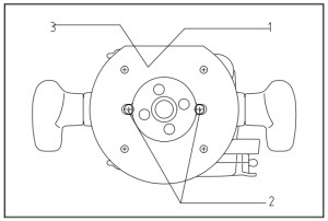
Installing or removing the bit
1. Shaft lock
2. Wrench
Caution
- Install the bit securely. Always use only the wrench provided with the tool. A loose or overtightened bit can be dangerous.
- Always use a collet suitable for the shank diameter of the bit.
- Do not tighten the collet nut without inserting a bit, or install small shank bits without using a collet sleeve. Either can cause the collet cone to break.
- Use only router bits whose maximum speed, as indicated on the bit, exceeds the router’s maximum speed.
Insert the bit into the collet cone. Press the shaft lock to keep the shaft stationary and use the wrench to tighten the collet nut securely. - When using router bits with a smaller shank diameter, first insert the appropriate collet sleeve into the collet cone and then install the bit as described above.
- To remove the bit, follow the installation procedure in reverse.
Operation
Caution
- Before operation, ensure the tool body automatically rises to the upper limit and the bit does not protrude from the tool base when the lock lever is loosened.
- Before an operation, ensure the chip deflector is installed properly.
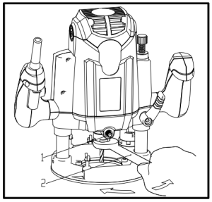
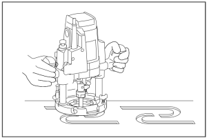
Always use both grips and firmly hold the tool by both grips during operations.
Set the tool base on the workpiece to be cut without the bit making any contact. Then turn the tool on and wait until the bit attains full speed. Lower the tool body and move the tool forward over the workpiece surface, keeping the tool base flush and advancing smoothly until the cutting is complete.
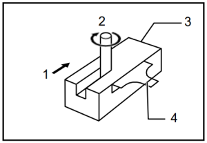
When cutting edge, the workpiece surface should be on the left side of the bit in the feed direction.
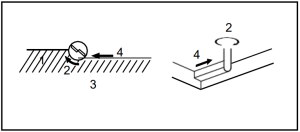
1. Workpiece
2. Bit revolving direction
3. View from the top of the tool
4. Feed direction
Note
- Moving the tool forward too fast may cause a poor quality cut or damage to the bit or motor. Moving the tool forward too slowly may burn and mar the cut. The proper feed rate will depend on the bit size, the kind of workpiece, and the depth of cut. Before beginning the cut on the actual workpiece, it is advisable to make a sample cut on scrap lumber. This will show exactly how the cut will look and enable you to check dimensions.
- When using the straight or trimmer guide, install it on the right side in the feed direction. This will help to keep it flush with the side of the workpiece.
1. Feed direction
2. Bit revolving direction
3. Workpiece
4. Straight guide
Straight Guide
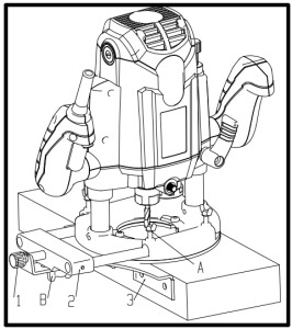
1. Fine adjusting screw2. Guide holder
3. Straight guide
4. Clamping screw(B)
5. Clamping screw(A)
The straight guide is effectively used for straight cuts when chamfering or grooving.
Install the straight guide on the guide holder with the clamping screw (B). Insert the guide holder into the holes in the tool base and tighten the clamping screw (A).
To adjust the distance between the bit and the straight guide, loosen the clamping screw (B) and turn the fine adjusting screw (1.5mm or about 1/16″ per turn).
At the desired distance, tighten the clamping screw (B) to secure the straight guide in place.
Templet Guide (optional accessory)
The templet guide provides a sleeve through which the bit passes, allowing use of the tool with templet patterns. To install the templet guide, pull the lock plate lever and insert the templet guide.
1. Templet guide
2. Lock plate
When cutting, move the tool with the guide roller riding the side of the workpiece.
1. Bit
2. Base
3. Templet
4. Workpiece
5. Distance (X)
6. Outside diameter of thetempletguide
7. Templet guide
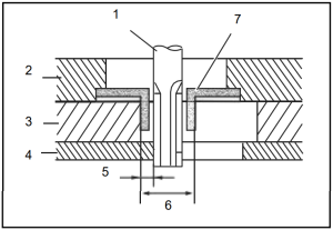
Note
- The workpiece will be cut a slightly different size from the templet. Allow for the distance (X) between the bit and the outside of the templet guide. The distance (X) can be calculated by using the following equation: Distance (X) = (outside diameter of the templet guide – bit diameter) / 2
Trimmer guide (optional accessory)
Trimming, curved cuts in veneers for furniture and the like can be done easily with the trimmer guide. The guide roller rides the curve and assures a fine cut.
Install the trimmer guide on the guide holder with the clamping screw (B). Insert the guide holder into the holes in the tool base and tighten the clamping screw (A). To adjust the distance between the bit and the trimmer guide, loosen the clamping screw (B) and turn the fine adjusting screw (1.5mm or 1/16″ per turn). When adjusting the guide roller upor down, loosen the clamping screw (C). After adjusting, tighten all the clamping screws securely.
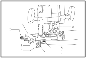
1. Guide holder
2. Adjusting screw
3. Clamping screw(B)
4. Clamping screw(C)
5. Trimmer guide
6. Clamping screw(A)
When cutting, move the tool with the guide roller riding the side of the workpiece.
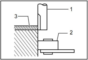
1. Bit
2. Guide roller
3. Workpiece
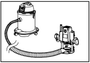
Dust nozzle set (Accessory)
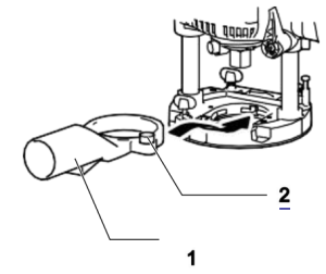
1. Dust nozzle
2. Clamping screw
Use the dust nozzle for dust extraction. Install the dust nozzle on the tool base using the thumb screw so that the protrusion on the dust nozzle fits the notch in the tool base. Then, connect a vacuum cleaner to the dust nozzle.
Maintenance
Caution
Always ensure the tool is switched off and unplugged before attempting to perform inspection or maintenance.
Replacing the carbon brush
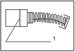
1. Limit mark
Remove and check the carbon brushes regularly. Replace them when they wear down to the limit mark. Keep the carbon brushes clean and free to slip into the holders. Both carbon brushes should be replaced at the same time. Use only identical carbon brushes.
Use a screwdriver to remove the brush holder caps. Remove the worn carbon brushes, insert the new ones, and secure the brush holder caps.
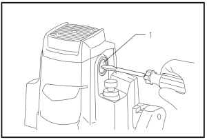
1. Brush holder cap
2. Screwdriver
After replacing brushes, plug in the tool and break in brushes by running tool with no load or about 10 minutes. Then check the tool while running and electric brake operation when releasing the switch trigger. If electric brake is not working well, ask your local service center for repair.
Recommended For Your Project
VEVOR Plunge Router, 3-1/4 HP, 120V, 12000-23000 RPM Manual

Reviews
There are no reviews yet.