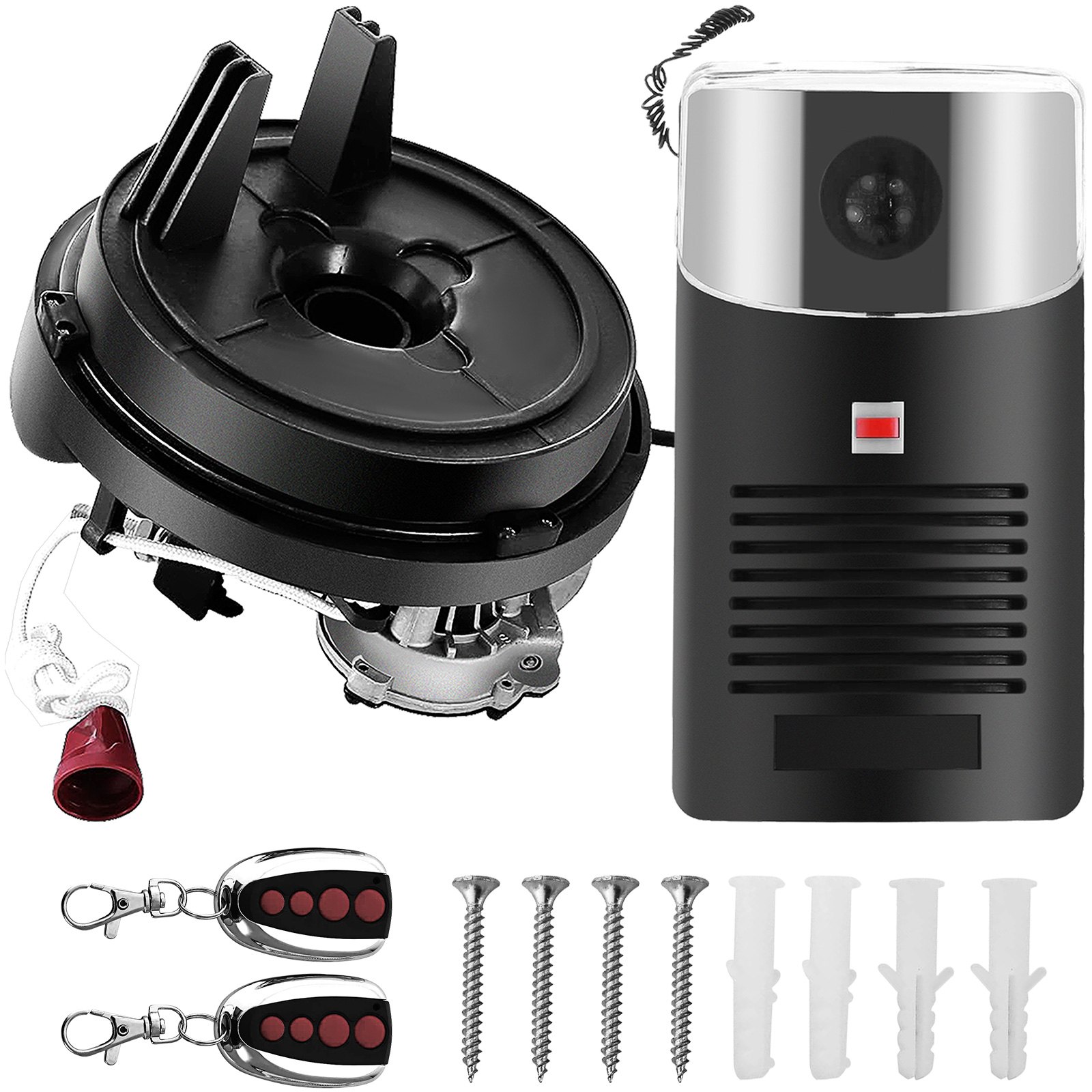
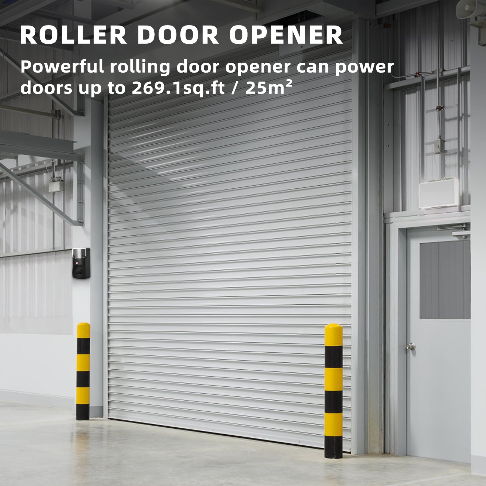
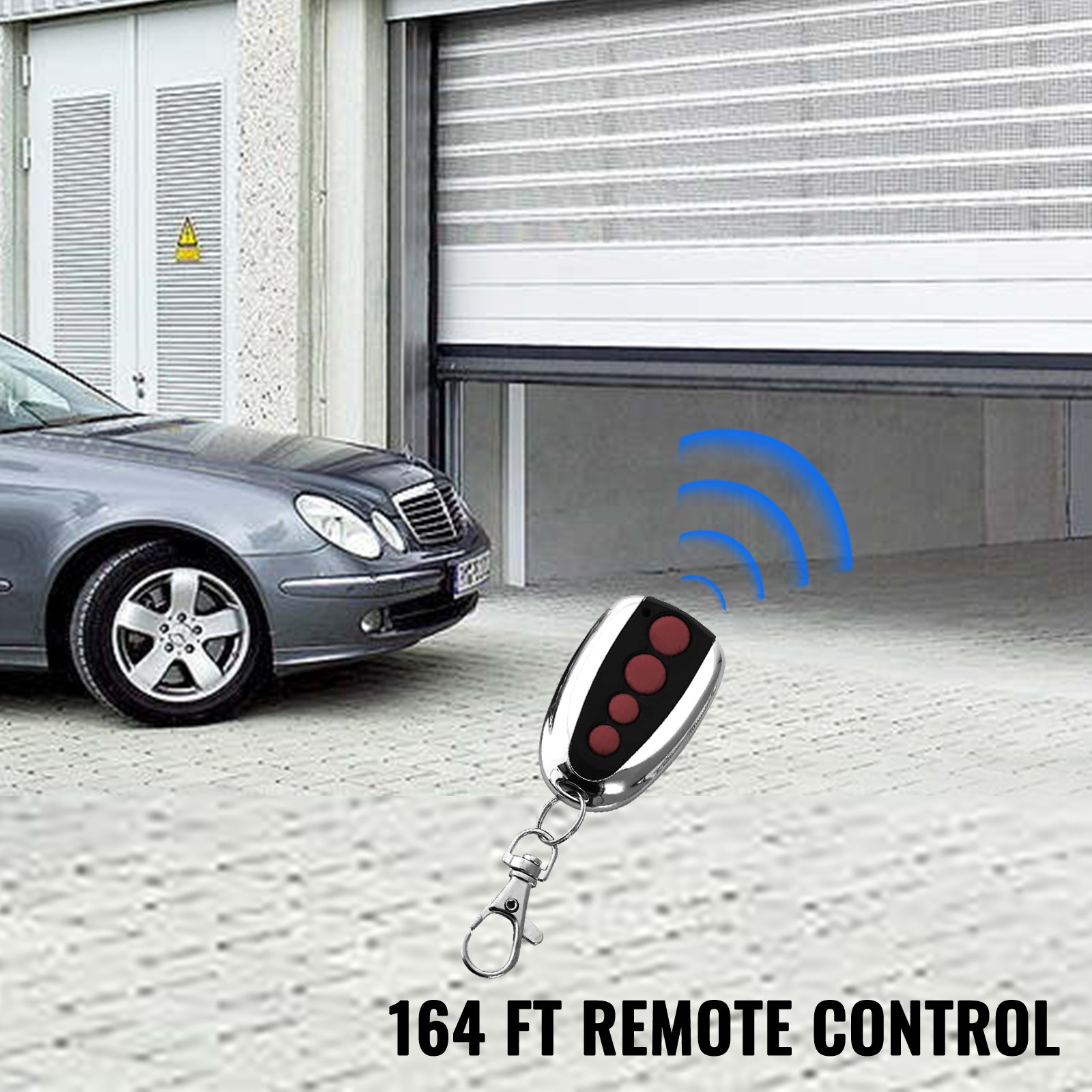
Unlock the full potential of your VEVOR Garage Roller Door Opener with our comprehensive product manual download. Designed specifically for the VEVOR Garage Roller Door Opener with 250 N lift force and 164 ft remote control range, this manual provides step-by-step instructions for setup, troubleshooting, and optimization.
Whether installing the 110V electric roller gate opener for the first time or needing guidance with the auto garage roller gate opener kit, this user-friendly guide is your ultimate resource. With detailed diagrams, clear instructions, and helpful tips, you’ll have everything you need to ensure your garage door opener operates smoothly and efficiently.
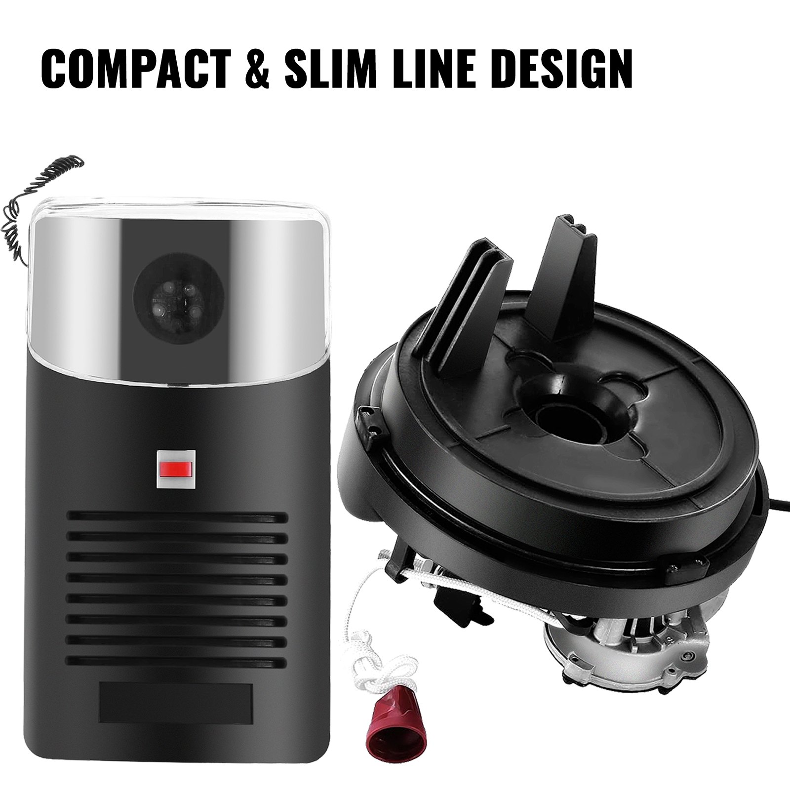
Perfect for both novice and experienced users, this manual will help you maximize the functionality and longevity of your VEVOR Garage Roller Door Opener, making it an indispensable tool for your garage or store.
ROLLER DOOR OPENER MANUAL
MODEL: YHDO-1
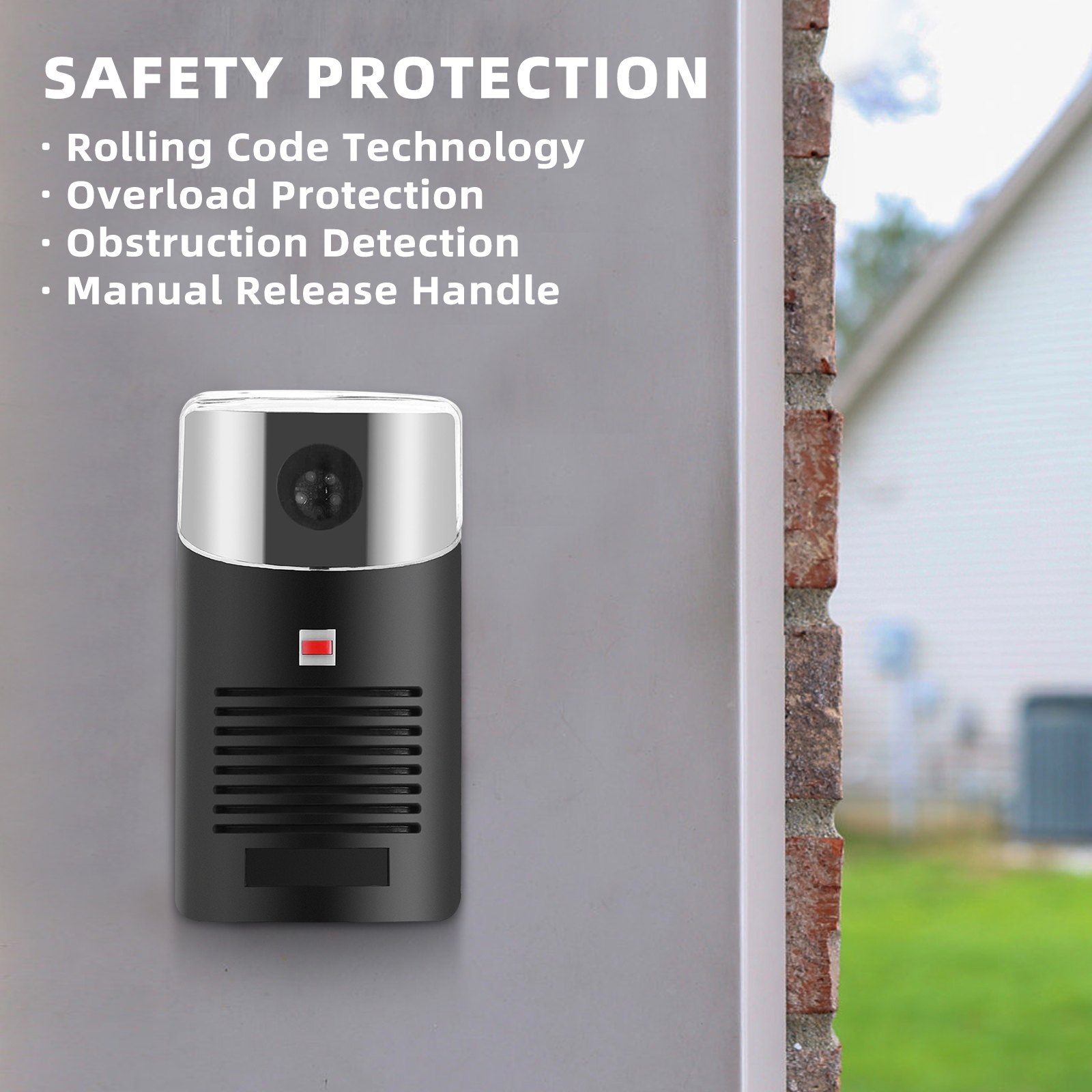
SAFETY WARNINGS
IMPORTANT: PLEASE READ THESE INSTRUCTIONS CAREFULLY BEFORE COMMENCING THE INSTALLATION OF THE ORERATOR UNIT
This Automatic opener has been designed to provide years of trouble-free use. However, it will only perform efficiently if installed and operated correctly.
READ THESE IMPORTANT SAFETY RULES FIRST
Keep the garage door balanced. Sticking or binding doors must be repaired. Garage doors, door springs, brackets, and hardware are under extreme tension and can cause serious personal injury. Do not attempt adjustment. Call for professional garage door service.
Do not wear rings, watches or loose clothing while installing or servicing a garage door operator.
Installation and wiring must comply with your local building and electrical codes.
The safety reverse system test is critical. Your garage door must reverse when it contacts a 5—to 10-cm-high object, which may result in serious personal injury from closing it. Repeat the test once a month and make adjustments if necessary (see sensitivity adjustment).
YHDO operator is an electronic obstruction system that provides safe and reliable operation. However, some countries also require the installation of a photoelectric sensor across the doorway. Please check this requirement with your local distributor.
Do not use the force adjustments to compensate for a binding or sticking garage door. Excessive force will interfere with the proper operation of the Safety Reverse System or damage the garage door.
This unit should be installed in a damp space.
Install the lighted door Control Box (or any additional Push Buttons) in a location where the garage door is visible but out of the reach of children. Do not allow children to operate push button(s) or remote control(s). Misuse of the operator may result in serious personal injury from a closing garage door.
⚠️ CAUTION
Activate the operator only when the door is in full view, free of obstructions, and properly adjusted. Do not enter or leave the garage while the door is in motion, and do not allow children to play near it.
Disconnect the electric power to the garage door operator before repairing or removing covers.
IMPORTANT: Fix the caution label to the rear of the garage door to remind drivers of safe operating procedures.
PREINSTALLATION NOTE
N.B: The right-hand and left-hand installations could be swapped if you wish. Please refer to the control box setup.
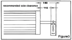
Check that there is sufficient side clearance to fit the operator unit. It may be fitted to either the right or left-hand side.
-
Minimum side clearance
The minimum side clearance between the door curtain and the inside edge of the mounting bracket is 85mm. The minimum side clearance between the door curtain and the outside edge of the mounting bracket is 135mm.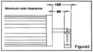
-
Recommended side clearance
The recommended side clearance between the door curtain and the mounting bracket is 110mm. The recommended side clearance between the door curtain and the mounting bracket is 160mm.
f the operator is being fitted at the same time as the new door installation, read these instructions in conjunction with the YHDO roller door installation instructions.
If the operator is being retrofitted, make sure the door operates smoothly and is properly balanced.
N.B.: SPECIAL CARE SHOULD BE TAKEN IF RE-TENSIONING OF THE DOOR IS REQUIRED.
At no stage should you loosen both “U” bolts if the door is under tension.
IF ANY PROBLEMS, PLEASE CONTACT YOUR LOCAL SUPPLIER OF THIS OPERATOR.
GARAGE ROLLER DOOR OPENER INSTALLATION INSTRUCTIONS
STEP 1
Whilst the door roll is on the floor, rotate the shaft backwards and forwards by hand and then release. This action will allow the roll to centralize itself on the shaft. (New installation only).
STEP 2
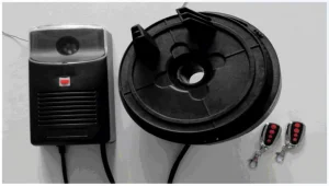
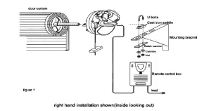
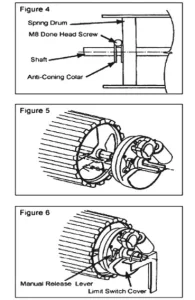
Slide the drive unit onto the shaft as shown in Figure 5, ensuring the drive lugs engage fully with the narrowest spoke on the drum wheel.
N.B.: Right-hand installation shown (inside looking out)
Lift the door onto the mounting brackets (ensuring the curtain roll is round correctly) and centralize the curtain roll with the opening. Refer to door installation instructions. (New installations only).
Ensure the motor assembly is fully engaged with the drum wheel spokes. Clamp the shaft to the mounting brackets using the “U” bolts supplied. (Use the “U” bolt in the opener pack for the MOTOR end.) See Figure 6.
Disengage the motor drive by pulling the manual release string downwards. See Figure 6.
Tension the door and complete the installation as per the Instructions. Ensure the door is correctly balanced and does not bind or stick within the vertical tracks.
Ensure locking bars (if fitted) are moved to the retracted (unlocked) position and keys removed from the lock.
Mount the Control Unit approximately 1.6m from the floor out of the reach of children. Use the NO.4×1” self-tapping screws and raw plugs supplied. Ensure the aerial is clear of all steel supports and coiled electrical leads. Fit the plug from the motor unit into the bottom of the Control Box.
Connect the control unit power cord to an adjacent socket. Ensure that the socket is properly earthed.
SETTING TOP AND BOTTOM LIMITS
N.B.: Right-hand installation only. If the left-hand limit switch is reversed.
STEP 1
Remove the Limit Switch Cover Plate (See Figure 6) by carefully removing it with a small screwdriver.
STEP 2
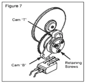
The top limit cam, “T,” controls the door’s open position, and the bottom limit cam, “B,” controls the door’s closed position.
STEP 3
Slightly loosen the three retaining screws
so that the cams can be easily moved (See Figure 7).
STEP 4
Ensure that the manual release lever is still in the “disengaged” position, and manually raise the door until it is approximately 100mm from the top stop position.
STEP 5
Rotate cam “T” (in the same direction it was moving when you manually raised the door) to actuate the top Limit Switch.
STEP 6
Manually lower the door until it is touching the ground.
STEP 7
Rotate cam “B” (in the same direction it was moving when you manually lowered the door) to actuate the bottom Limit Switch.
STEP 8
Tighten the three retaining screws so that the cams will not move.
STEP 9
Manually position the door halfway and re-engage the motor drive by moving the manual release lever to the “engage” position.
N.B. The Door can now only be operated electrically, not manually. If you wish to return to manual operation, ensure the power is switched off and move the lever to the “disengage” position.
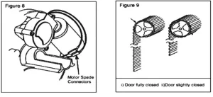
IMPORTANT: Hold the bottom rail when the door travels in the “Up” position. The door should overload and stop. If it does not, reverse motor wires (Spade Connections). You must re-adjust the Limit Cams as they will be working in a different direction.
STEP 10
Press the Button on the Control Box Front and check the closing and stopping position.
STEP 11
If you achieve the desired stop position, replace the Limit Switch Cover Plate. If not, reset the Limit Cams (STEP 2 to 9) after first turning off the mains power.
STEP 12
Once the limits have been set, fit the additional security screws (2 off self-tapping screws supplied) with the door in manual mode. With the door fully closed, mark the panel at the first point where the curtain roll touches the drum wheel on both ends of the curtain (See figure 9).
Raise the door slightly so the marks can be seen and accessed inside the garage.
Fit the security screws through the bottom of the corrugation and into the plastic flange of the drum wheels at both ends of the curtain. Tighten securely.
⚠ WARNING! – Do not run the door on power through its full travel until the limits are correctly set.
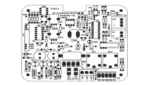
CONTROL BOX SET UP
Remove the cover on the front of the control box.
- Wiring diagrams
B1, B2 (AC24V): Transformer output
M1, M2 : Motor
X4(+24) : Infrared beam, X41, signal input
LAMP : 36V 1.5W light socket
X3 : Remote control receiver
- Auto close option
Switch 1 (1) in “on” position: auto close features on;
Switch 1 (1) in “off” position: auto close features off;
NB: Mandatory Photo Eye Protection must be used for this option.
Contact your local supplier.
- Right-hand and left-hand installation swap
Switch 1(2) in “on” position is for right-hand installation;
Switch 1(2) in the “off” position is for left-hand installation.
- Sensitivity adjustment
For right-hand installation:
- Adjust pot RF2 for downward traveling sensitivity; clockwise is for a significant force, and counterclockwise is for a small force.
- Adjust pot RF2 for upward traveling sensitivity. Clockwise is for a big force, and anti-clockwise is for a small force.
While the door is travelling, turn the obstruction sensitivity pot slowly until an overload condition occurs, i.e., the door goes up but stops before reaching the set top limit or goes up a few times, ensuring an overloading condition is not registered during regular operation.
PROGRAMMING HANDSETS FOR THE NEW CONTROL BOX
Press and release the black learning button. The learning LED indicator will light and go out. Then press the handset key, which will operate the door. The handset transmitter is now programmed.
For multiple handsets, do the same as mentioned above.
To delete all codes
Press and hold the learning button in the control box for 15 seconds until the LED indicator goes out. All the transmitter codes held in memory have been erased.
NB: If a transmitter is lost or stolen, please erase the memory and relearn any spare or new transmitters.
OWNER’S MANUAL
DOOR OPERATION
Any of the following two methods may operate a roller door equipped with a roller door operator:
- By using the handheld transmitter.
- Press the push button on the control box (mounted on the wall).
WARNING
Ensure the center lift lock is not engaged when the drive unit is in automatic.
Manual Operation.
In the case of a power failure, the drive unit has an easily accessible manual release string. The door can be opened manually using the release string.
Obstruction Detection
During an open cycle, the door will stop if an obstruction is detected.
During a closing cycle, the door will reverse to the open position if an obstruction is detected.
The sensitivity or the amount of force required to cause an obstruction detection is fully adjustable.
Courtesy Light
An internal courtesy light is housed within the control box enclosure. This is activated during an open or closed cycle and will stay illuminated for approximately 3 minutes.
Automatic Closing
The operator can be programmed to automatically close from 5 to 60 seconds after opening the door.
Photo-electric sensor
The operator includes an interface for connecting a photo–beam sensor.
The Photo-beam sensor can be supplied as an accessory.
OPERATING CONDITIONS
- Control Box Push Button
Pressing this button will open, close, or stop the door
- Hand transmitter
Each button is programmed to have three functions: open, close, and stop the door.
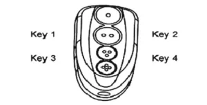
Key Ring Handset (optional)
The hand transmitter uses the latest surface mount technology and incorporates four functional buttons. This enables the user to control up to 4 separate operators from one handset remotely.
TROUBLE SHOOTING THE GARAGE ROLLER DOOR OPENER
DOOR WILL NOT OPERATE FROM
A) Control Box
- Check the power on the control unit (red LED illuminated).
- IF NOT, check the main plugs and fuse.
- Plug is fully engaged on top of the Control Box.
- Motor wiring connections are properly engaged.
- Manual release lever in ‘engaged’ position.
- Limit Switch cams correctly set i.e upper Limit Switch for fully open position, lower Limit.
- Switch to the fully closed position.
- Move the door manually to a half-closed position and try again.
- Try the operation with the Hand Transmitter.
B) Transmitter
- Check that the door operates correctly using the Push Button on the Power Head to prove that the system is working properly.
- Try recoding the Transmitter.
- Check that the battery in the Transmitter is correctly fitted. The LED should illuminate.
- Try a new battery.
- Move the aerial manually and try in different orientations, keeping it away from steel structures and electrical cables.
DOOR OPERATES BUT FAILS TO OPEN OR REVERSE BEFORE FULLY CLOSED
- Check the manual operation for correctness. Balance the door manually to ensure it is not binding. Adjust if necessary.
- Spray silicone lubricant, do not grease.
- Check and adjust the safety sensitivity setting.
- Check Limits.
BANGS HARD ON TRACK AND STOPS WHEN FULLY OPEN
- Check the top Limit Switch setting.
- Adjust if necessary.
BANGS HARD ON GROUND AND REVERSES WHEN FULLY CLOSED
- Check the bottom Limit Switch setting.
- Adjust if necessary.
DOOR FAILS TO TRAVEL DOWN FROM OPEN POSITION – MOTOR RUNS AND ROLLER DOOR STOP MOVING
- Check the door curtain has smoothly entered the tracks, as near vertical as possible.
- Check door tension, ensure it is tight, and reduce spring tension if necessary.
- If the above methods do not work well, the door may require a weight bar to be fitted.
SHORT-RANGE REMOTE CONTROL
- The remote control should have a minimum of 8m range.
- Check that the battery is correctly fitted in the Transmitter.
- Try a new battery.
- Move aerial and try in different orientations, avoiding steel structures and electrical cables.
DOOR OPERATES BUT FAILS TO OPEN FULLY, BUT REVERSES TO THE CLOSED POSITION
- Reset Limits.
- Re-adjust Sensitivity Adjustment.
POWER FAILURE
- To disengage.
- Pull the manual release string downwards (refer to Fig. 13).
- To engage.
- Push the manual release string up.
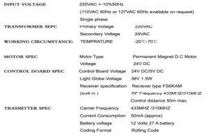
Technical Specifications
GARAGE ROLLER DOOR OPENER ACCESSORY OPTIONS
- Additional remote control transmitter.
- Infrared beam: an Additional safety feature.
- Manual release lock.
- External receiver.
Recommended For Your Project
VEVOR Garage Roller Door Opener, 250 N Lift Force 164 ft Remote Control, 110V Manual
Reviews
There are no reviews yet.