
Unlock the full potential of your VEVOR Dual Swing Gate Opener Heavy Duty Automatic Gate Opener with our comprehensive product manual download. Designed to accommodate gates up to 880 lbs and 18ft long, this 80W AC-powered automatic gate opener comes with a complete kit, including a remote for effortless control.
Our detailed manual covers every setup, troubleshooting, and optimization aspect, ensuring a seamless installation and operation experience.
Whether pushing or pulling to open the dual gate opener at a speed of 16mm/s, our guide provides step-by-step instructions and expert tips to maximize efficiency and longevity. Download now to access valuable insights and ensure your gate opener performs at its best.
Dual Swing Gate Opener
Models: MK1101/ MK1102MK1301/ MK1302MK1101M/ MK1102MMK1301M/ MK1302M/ MK1501M/ MK1502M
Safety Installation Information
- READ and FOLLOW all instructions.
- The gate opener is intended for use with Class I vehicular swing gates. Class I denotes a vehicular gate opener (or system) for dwellings, garages, or parking areas. Install the gate opener only when it is appropriate for the gate’s construction and usage class.
- Gate opening system designers, installers, and users must consider the possible hazards associated with each individual application. Improperly designed, installed, or maintained systems can create risks for the user and bystander. Gate system design and installation must reduce public exposure to potential hazards. All exposed pinch points must be eliminated or guarded.
- A gate opener can create high levels of force during regular operation. Therefore, safety features must be incorporated into every installation. Specific safety features include safety sensors.
- The gate must be installed appropriately and work freely in both directions before the installation of the gate opener.
- The gate must be installed in a location so that enough clearance is provided between the gate and the adjacent structure when opening and closing to reduce the risk of entrapment. Swinging gates shall not open into public access areas.
- The opener is intended for use only on gates used for vehicles. Pedestrians must be supplied with a separate access opening. The pedestrian access opening shall be designed to promote pedestrian usage and located such that persons will not come in contact with the moving vehicular gate.
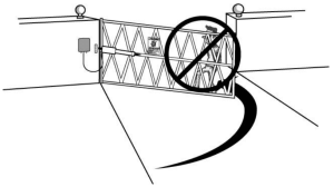
- Pedestrians should never cross the pathway of a moving gate. The gate opener is not acceptable for use on any pedestrian gate. Pedestrians must be supplied with separate access.
- For an installation utilizing non-contact sensors (safety sensors), see the product manual on the placement of non-contact sensors (safety sensors) for each type of application.
Care shall be exercised to reduce the risk of nuisance tripping, such as when a vehicle trips the safety sensor while the gate is still moving.
One or more non-contact sensors (safety sensors)shall be located where the risk of entrapment or obstruction exists, such as the perimeter reachable by moving gate or barrier.
- Never mount any device that operates the gate opener where the user can reach over, under, around, or through the gate to operate the controls. Controls must be placed at least 6’ (1.8m) from any part of the moving plate.
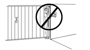
- Controls intended to reset an operator after 2 sequential activations of the entrapment protection device or devices must be located in line of sight of the gate, or easily accessible controls shall have a security feature to prevent unauthorized use. Never allow anyone to hang on or ride the gate during the entire gate travel.
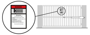
- Each gate opener is provided with two safety warning placards. The placards are to be installed on the front and back of the gate, where they are visible. The placards may be mounted using cable ties through the four holes on each placard. All warning signs and placards must be installed where visible in the gate area.
- Contact underground utility locating companies BEFORE digging to avoid damaging gas, power, or other underground utility lines.
- Do not permit children to play on or around the gate, and keep all controls out of their reach
Dual Gate Opener Parts List
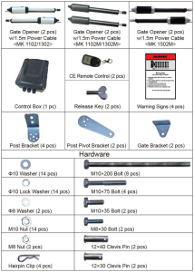
Single Gate Opener Parts List
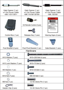
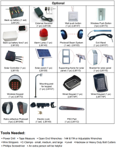
Optional Accessories Parts List
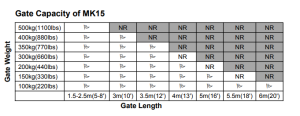
Technical Specifications & Features

Features of the Dual Swing Gate Opener
- Soft start and soft stop.
- Emergency release key in case of power failure.
- Dual/Single gate running mode.
- Adjustable opening/closing interval between the master and slave gate.
- Stop in case of obstruction during gate opening.
- Reverse in case of obstruction during gate closing.
- Built-in adjustable auto-close (0-99 seconds).
- The built-in max. Motor running time (MRT) is adjustable for multiple safety protections (1-50 seconds).
- Digital display indicates the running situation and the setting menu.
- Can be equipped with a wide range of accessories.
- Reliable electromagnetism limit for easy adjustment.
- Easy to install and with minimum maintenance requirements.
Dual Gate Overview
Single Gate Overview
Preparation for Installation
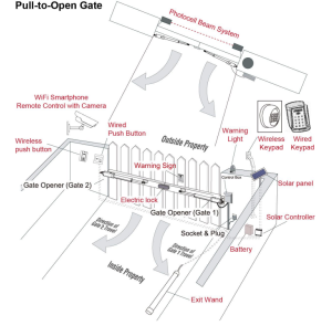
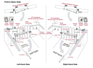
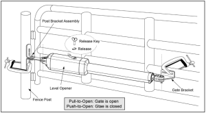
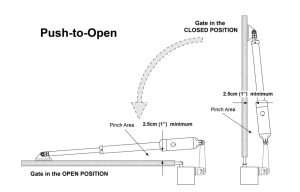
There are two installation types for the gate opener: Pull-to-Open and Push-to-Open.
In the push-to-open installation, the gate opens from the property. Each gate must have a push-to-open bracket (PSO part).
NOTE: Ensure the gate does not open into public areas.
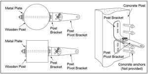
The gate opener is mounted to the gate and the gate post. Both round and square posts can be used because the Post Brackets are curved. When mounting the Post Brackets, use bolts long enough to pass through the entire post. M10 x 200 bolts are included. Concrete anchors are not provided.
When mounting the Post Brackets to wooden posts, a larger-size washer or metal plate should be used between the bolts and the wooden post to ensure the stability of the fastening hardware. If the post is smaller than 6″ in diameter or square, it should be made of metal and set in cement to ensure stability.
Install the Gate Opener on the Gate
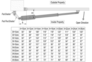
The position of the Post Bracket is significant. The following illustrations and tables are required to determine the proper mounting position for the Post Bracket. The tables show the maximum opening angle of the gate for a given A and B. For example, if A is 16cm and B is 14cm, the maximum opening angle of the gate is 110°
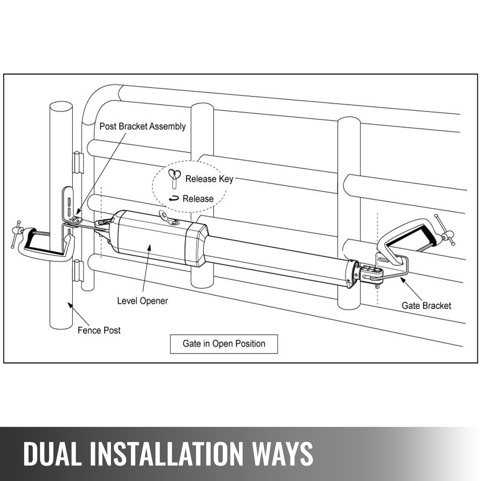
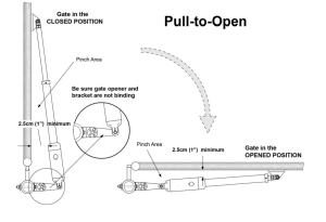
Pull-to-Open Installation — Gate in Closed position (Moving-Rod is extended)
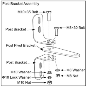
- Insert the M10 x 35 bolt through the center hole of the post bracket and post pivot bracket as shown. Place a ¢10 washer, ¢10 lock washer, and M10 nut on the bottom of the bolt and hand-tighten.
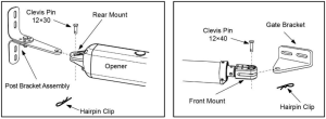
- Attach the gate bracket and post bracket assembly to the opener by inserting a clevis pin. Secure the clevis pins using the hairpin clips.
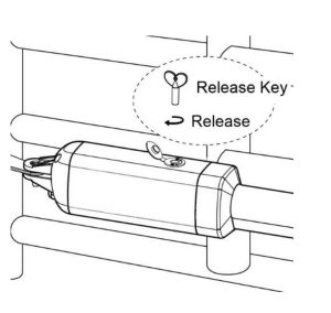
- Open the release hole plug on the top of the gate opener, insert the release key, and turn the key 90° clockwise. This releases the motor and allows the push-pull rod to be manually extended and retracted. To restore regular operation, turn the key 90° counterclockwise.
- With the opener fully retracted and with the gate in the fully open position (for Pull-to-Open installation) or fully closed position (for Push-to-Open installation), place the gate opener with the Post Bracket Assembly and Gate Bracket on the gate post and the gate. Position the Post Bracket Assembly and Gate Bracket so the gate opener is level. While holding the gate opener in the level position, temporarily secure it with two.
- Ensure that there is a minimum clearance of 2.5cm between the gate and the opener and that the opener and the Post Pivot Bracket are not binding in both the gate-open and gate-closed positions. If there is not at least 2.5cm of clearance or if the opener and the Post Pivot Bracket are binding, rotate the Post Pivot Bracket and/or move the Post Bracket Assembly to obtain the minimum clearance and eliminate the binding. When the minimum clearance has been obtained and any binding has been eliminated, place the M8 x 30 bolt through the aligned holes in the Post Bracket and the post pivot bracket.
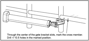
- Sign the bolt-hole point on the gate bracket and gate. Do this by placing a punch or a sign in the middle of each bolt slot on the post bracket assemblies and the gate bracket. It allows slight adjustments to the post bracket. Then, remove the post and gate brackets by removing the C-clamps.
- Drill 10.5 mm diameter holes through the post and the gate at the marked locations.
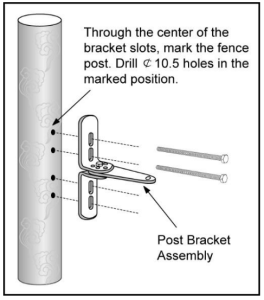
- Attach the post bracket assemblies to the gate posts by inserting M10 x 200 bolts through each post bracket assembly and the drilled holes in the gate posts. Fasten each bolt with one ¢10 washer, one ¢10 lock washer, and one ¢10 nut.
- Attach the gate brackets to each gate by inserting two M10 x 75 bolts through the gate brackets and the drilled holes. Fasten each bolt with one ¢10 lock washer and one ¢10 nut.
- Cut off any part of the bolts that extend beyond the tightened nuts.
- With the gate opener fully retracted and with the gate in the fully open position (for Pull-to-pen installation) or fully closed position (for Push-to-Open installation), attach the gate opener to the Post Bracket Assembly and the Gate Bracket by inserting a clevis pin through the gate opener and the Post Pivot Bracket and another clevis pin through the gate opener and the Gate Bracket. Secure each clevis pin with a hairpin clip.
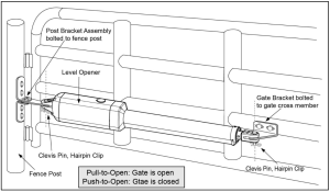
Open the release hole plug on the top of the gate opener, insert the release key, and turn the key 90° counterclockwise. This restores normal operation.
NOTE: The control board should be set to the PULL/PUSH TO OPEN following the installation.
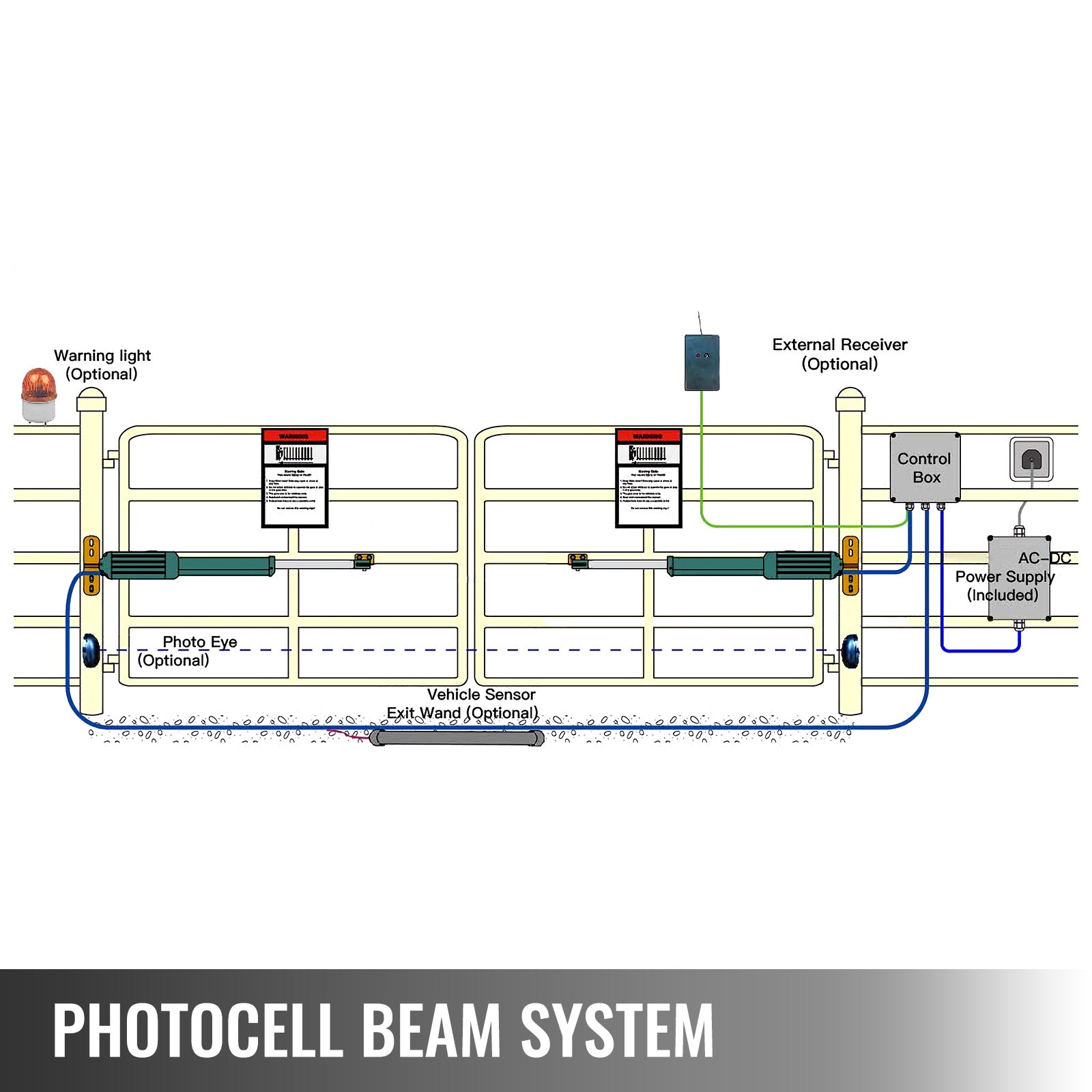
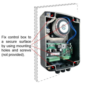
Mounting of the Control Box
To install the control box use the deck screws (not provided). Even though the control box is waterproof, for safety reasons and a longer service life, it is recommended to install the control box inside a
secure surface and at least 100 cm (40 inches) above the ground to avoid being flooded or buried under snow.
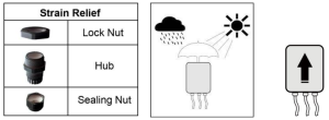
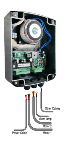
Insert the power cable and cable of the first gate opener through the front strain relief and into the control box by loosening the strain relief screw located in the leftmost part of the outside bottom of the control box and feeding the cables into the control box. Check that the cables are long enough to reach their respective terminal blocks in the control box.
CAUTION:
- Install the control box in a well-ventilated place protected against rain and sunlight.
- Insert the cable of the second gate opener and alarm lamp cables into the control box through the middle strain relief. Then repeat step 2.
- Insert other cables into the control box through the rightmost strain relief. Then repeat the step
NOTE: Only motor cables (1.5m length) are provided. Other cables are subject to site installation requirements and are not provided.
CAUTION: Make sure the cable outlet hole in the Control Box is always down during installation to drain off the water.
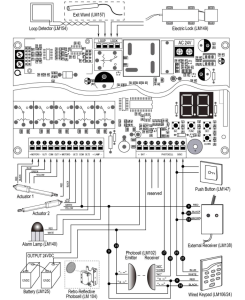
Connection of the Power Supply
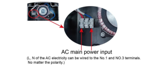
WARNING: NEVER connect the gate opener to the power outlet before all the installations have been done. The live line and the neutral line should be connected to the power input terminals, as shown in the photo below, regardless of polarity. The wire (not provided) size should be at least 0.75mm2 (18AWG), which is intended to connect the power supply.
Connection of the Control Board
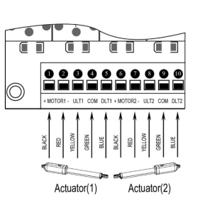
Motor connection for PULL-TO-OPEN
Actuator 1
Insert the stripped cable wires into the appropriate terminals on the opener terminal block. The red wire should be inserted into the “MOTOR1+” terminal, the black wire into “MOTOR1-“, the blue wire into ULT1, the green wire into COM, and the yellow wire into DLT1 terminal.
Actuator 2
Similar to the connection of Actuator 1, insert the stripped cable wires into the appropriate terminals on the opener terminal block. The red wire should be inserted into the MOTOR2+ terminal, the black wire into MOTOR2-, the blue wire into ULT2, the green wire into COM, and the yellow wire into DLT2 terminal.
NOTE: It is recommended that Gate Opener 1 be installed in the Master Gate and Gate Opener 2 in the Slave Gate.
Motor connection for PUSH-TO-OPEN
The connection of the motors’ power and limit wires by “Push to Open” differs from the connection by “Pull to Open.” So, motor 1 and 2 wires should be connected to the control box as instructed on the right.
The black wire should be inserted into the Motor+ terminal, the red wire into the Motor terminal, the yellow wire into the ULT1 terminal, the blue wire into the DLT1 terminal, and the green wire into the COM terminal.
Alarm Lamp (optional)
The red wire of the alarm lamp should be inserted into either LAMP (#11) terminal, the white wire into the other one (#12).
Back-up Battery (optional)
The “24V+” of the battery should be wired to the BAT+ (#13) terminal, and “24V-” should be wired to the BAT-(#14)terminal.
We strongly recommend using the controller LM118 (WA4004)to connect the Battery to the control board’s battery terminal if the battery is used as the primary power supply in the system (such as SOL PLUS KIT). Please refer to the separate user manual of control LM118 (WA4004).
Photocell Beam System (PBS) (optional)
Use a 2-core cable to connect the “- ~” terminal of the photocell’s emitter to the “14” terminal, the “+~” terminal to the “9” terminal. Also, the “- ~” and “+ ~” terminals of the photocell’s receiver should be connected to the “14” and “9” terminals in parallel. Use another 2-core cable to connect the “COM” terminal of the receiver to the “17” terminal, and the “NC” terminal to the “18” terminal.
Push Button (optional)
The push button should be wired to the “19” and “20” terminals. The gate operator works alternately by pushing the button (open-stop-close-stop-open).
Loop Detector (optional)
First, insert the LOOP DETECTOR BOARD into the CONTROL BOARD and then connect it to the control board. For detailed instructions, please refer to the manual for the LOOP DETECTOR.
Exit Wand (optional)
Please refer to the manual instructions for the EXIT WAND.
Electric Lock (optional)
The electric lock should be wired to the “LOCK” terminal.
External Receiver (optional)
The BROWN wire of the external receiver should be connected to the “19” terminal. The BLACK wire of the external receiver should be connected to the “20” terminal. The RED wire of the external receiver should be connected to the “9” terminal.
Wired Keypad (24VDC) (optional)
The RED wire of the wired keypad should be connected to the “9” terminal. The BLACK wire of the wired keypad should be connected to the “14” terminal. The WHITE wire of the wired keypad should be connected to the “19” terminal. The BLUE wire of the wired keypad should be connected to the “20” terminal.
Solar Panel (optional)
Please refer to the manual instructions of the solar panel and controller (LM118), which are separated.
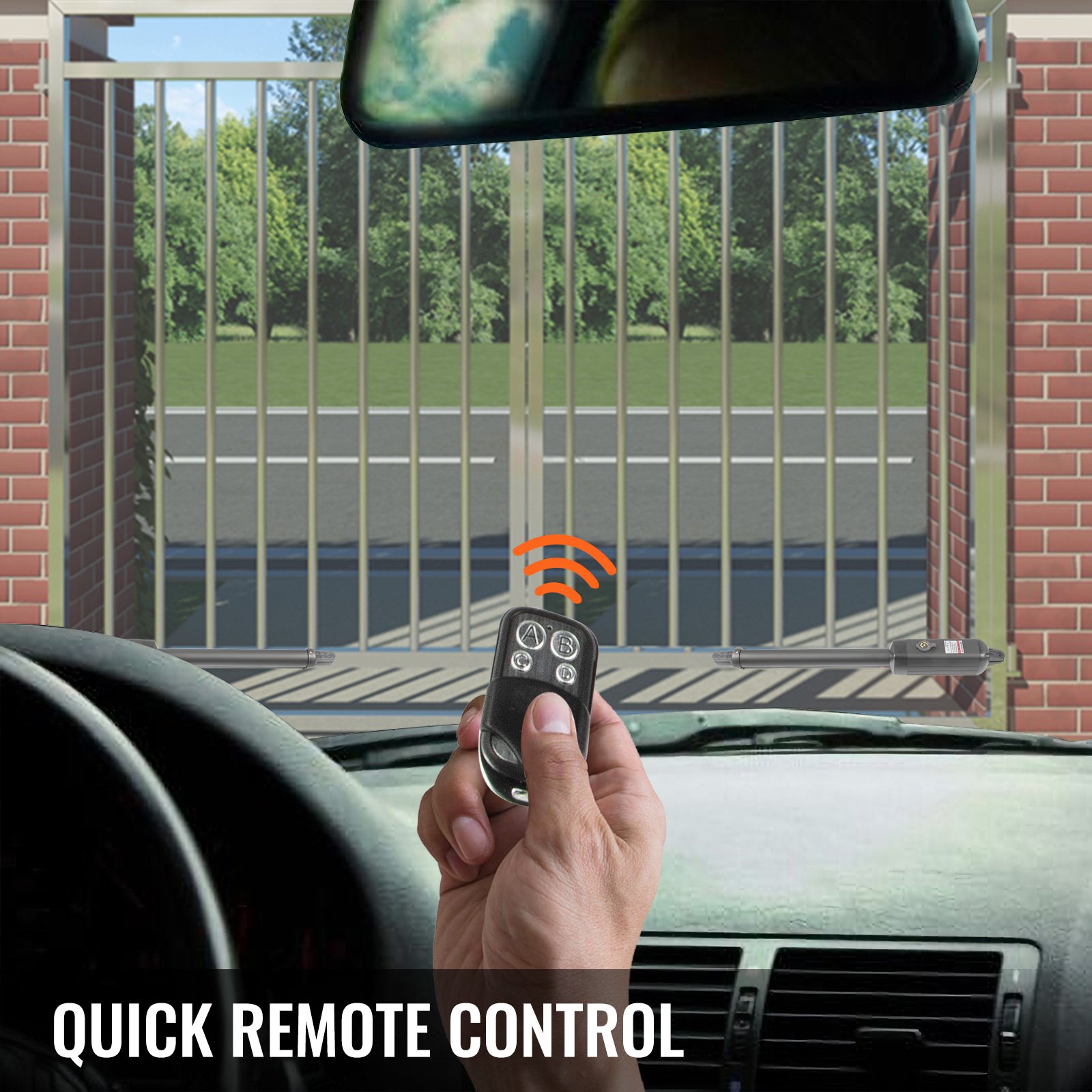
How to learn or erase the Remote
Learn the remote
Press and release the learn button; the LED will display “Ln.” Then press the key in the remote twice in 2 seconds; the LED will flash “Ln” for 4 seconds, then back to “- -.” Now, the remote has been learnt successfully.
WARNING: Activate the opener only when the gate is in full view, free of obstruction, and properly adjusted. No one should enter or leave the gate area while the gate is in motion. Do not allow children to operate the pushbutton or remote, and do not allow children to play near the door.
Your swing gate opener receiver and remote control transmitter are set to a matching code. The gate opener must be programmed to accept the new remote code if you purchase additional remote controls.
Erase all the remote codes
Press and hold the learn button until the LED displays “dL.” Release the button, and the LED will be back to “- -.” Now, all remote codes have been erased.
Caution: If you lose one of the remote controls, please learn all the other remote controls to have a new code for them.
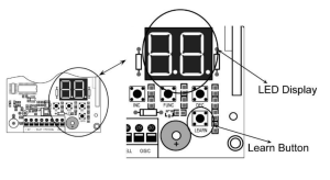
Setting of the Control Board
- Check again for the completed and correct assembly of your swing gate opener and gate.
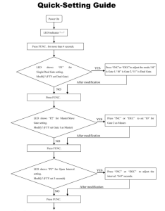
Plug the Power Grounded Cord into the nearest AC outlet. The Digital Display on the Control Board will flash with “- -”. The unit is in standby.
- Single/Dual Gate Set
Press and hold the “FUNC” button for more than 4 seconds. The Digital Display will indicate “P1”. The gate opener is on the SINGLE/DUAL Gate setting. Press the “INC” and “DEC” buttons respectively to the following modes: “01” is shown in the Digital Display, and it is Single Actuator 1 (Gate 1) mode. “10” shown in Digital Display, it is Single Actuator 2 (Gate 2) mode. “11” shown in Digital Display, it is Dual Actuator mode. Press the “FUNC” button to store the data when the single or dual gate is chosen. The Digital Display will
indicate “P2”. Now the single/dual gate set is finished. (Factory set is “11”)
- Master/Slave Gate Set
When Digital Display indicates “P2”, the gate opener is on the Master/Slave Gate Setting. Press the“INC” and“DEC” Buttons respectively to follow modes: “01” shown in Digital Display, which means Gate Opener 1 (right-hand side) as Master one “10” shown in Digital Display, which means Gate Opener 2 (left-hand side) as Master one Press the “FUNC” button to store the data when the master/slave gate is chosen. The Digital Display will indicate “P3”. Now the Master/Slave Gate Set is finished. (Factory set is “01”)
- Set the Open Interval between the Master and Slave Gate
When the Digital Display indicates “P3,” the gate opener is on the Open Interval between the Master and slave gate Settings. The open interval can be adjusted by pressing the “INC” and “DEC” Buttons. The Digital Display will show “0”-“9”, which indicates the interval time. “0” means the Master and Slave gates open simultaneously.“1” means the Master Gate starts to open one second before the Slave gate begins to open.
The max open interval is 9 seconds. Each time you press and release the “INC” button, the figure increases by 1, and the Master gate starts to open 1 second earlier. Each time you press and release the “DEC” button, the figure decreases by 1, and the interval decreases by 1 second.
(Factory set is 3 seconds)
Press the “FUNC” button to store the data when the open interval is set. The Digital Display will indicate“P4”. Now the Open Interval Set is finished.
- Set the Close Interval between the Master and Slave Gate
When the Digital Display indicates “P4,” the gate opener is on the Close Interval between the Master/Slave Gate Setting. The close interval can be adjusted by pressing the “INC” and “DEC” buttons. The Digital Display will show “0”-“9”, which indicates the interval time.”0” means the Master and Slave gates open simultaneously. ”1” means the Slave Gate starts to close one second before the Master Gate starts to close.
The maximum close interval is 9 seconds. Each time you press and release the “INC” button, the figure increases by 1, andtheSlave gate starts to close 1 second earlier. Each time you press and release the “DEC” button, the figure decreases by 1, and the interval decreases by 1 second. (Factory set is 3 seconds)
Press the “FUNC” button to store the data when the close interval is set. The Digital Display will indicate“P5.” The Close Interval Set is finished.
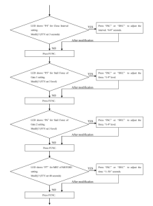
- Adjust the Obstruction Sensitivity/Stall Force
When the Digital Display indicates “P5”, the gate opener is on the Stall Force Adjustment.
Without a properly installed safety reversal system, the person (particularly small children) could be SERIOUSLY INJURED or KILLED by a closing gate.
- Too much force on the gate will interfere with the proper operation of the safety reversal system.
- NEVER increase force beyond the minimum amount required to close the gate.
- NEVER use force adjustments to compensate for a binding or sticking gate.
- If one control (force or travel limits) is adjusted, the other control may also need adjustment.
- After ANY adjustments are made, the safety reversal system MUST be tested. The gate MUST BE TESTED. The gate MUST reverse on contact with a rigid object.
The opener is equipped with an obstruction-sensing feature. If the gate encounters an obstruction, the opener will automatically reverse direction and stop. Based on the length and weight of the gate, it may be necessary to make force adjustments. The force adjustment should be high enough that small objects such as branches or wind will not cause nuisance interruptions, but low enough to prevent serious injury to a person or a vehicle.
a. Adjust Stall Force of Gate Opener 1
Now we adjust the stall force of gate 1
The stall force of gate opener 1 is adjusted by pressing the “INC” and “DEC” buttons respectively. TheDigital
Display will show “1”-“9”, which indicates the stall force levels. “1” means the minimum force, and“9” is the maximum force. Each time you press and release the “INC” button, the figure increases by 1, and the force increases to a higher level. Each time you press and release the “DEC” button, the figure decreases by 1, and the force decreases to a lower level. Press “FUNC” to store the data. The Digital Display will indicate“P6”. Now the force of gate opener 1 is finished. (Factory set is Level 3)
b. Adjust Stall Force of Gate Opener 2
When the Digital Display indicates “P6”, you can adjust the force of the gate opener 2. Please perform the same procedure as gate opener 1 (6-a). Press the “FUNC” button to store the data when the stall force of gate opener 2 is set. Then “P7” will be shown on the Digital Display.
NOTE: You may need to increase the stall force in cold weather due to increased resistance from gate hinges. The gate opener’s opening/closing force is adjusted automatically according to the stall force adjustment.
- Adjust the Max Motor Running Time (MRT) of the MOTOR for the gate opener
The maximum running time of the MOTOR can be set to make the motor stop running after a specified period even if the limit switch is invalid or the clutch is detached.
a. Adjust the MRT of MOTOR 1
When the Digital Display indicates “P7,” you can adjust MOTOR1’s MRT by pressing the “INC” and “DEC” buttons, respectively. The Digital Display Will show “01”-“50,” which indicates the MRT of MOTOR1 from 1 to 50 seconds.
You can hold the “INC” or “DEC” button for over 1 second to speed up the setting. Press the “FUNC” button to store the data when you finish setting. The Digital Display will indicate “P8”. (Factory default setting is “40” seconds)
b. Adjust the MRT of MOTOR 2
When the Digital Display indicates “P8”, you can adjust the MRT of MOTOR2. Please perform the same procedure as adjusting MOTOR1 (7-a). Press the “FUNC” button to store the data when you finish setting. The Digital Display will indicate“P9”. Now, MOTOR2 adjustment is finished.
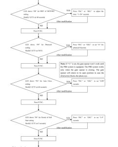
- Set the Safety Photocell Beam System (PBS) (Optional)
When the Digital Display indicates “P9”, the gate opener enters PBS set mode.
Press and release the “INC” or “DEC” button to set or shut off the PBS function. The Digital Display indicates “11”, the PBS is available. The Digital Display indicates “00”, the PBS is null.
Press the “FUNC” button to store the data when the PBS is set. The Digital Display will indicate “PA”. (Factory set is “00”)
- Set the Automatic Closing Time
When the Digital Display indicates “PA”, the gate opener enters into the setting of automatic closing time mode. Press and release the “INC” or “DEC” button, and the Digital Display will show a “01”-“99” button, which indicates the current automatic closing time. The minimum time is 1 second, and the maximum is 99 seconds.
Each time you press and release the “INC” button, the figure increases by 1, and the timing increases by 1 second. Each time you press and release the “DEC” button, the figure decreases by 1, and the timing decreases by 1 second. When the timing is “00”, the automatic closing function is shut off, and the gate will stay open. (Factory set is 60 seconds)
Press the “FUNC” button to store the data when setting the desired automatic closing time. The Digital Display will indicate “Pb”
- Set the Period of Soft Start
When the Digital Display indicates “Pb”, the gate opener is ready for the setting period of soft start. Press the “INC” or “DEC” button to set the soft start period. There is 1-9 seconds available in setting. Press the “FUNC” button to store the data when the period is set. The Digital Display will indicate“PC”. (Factory set is 3 seconds)
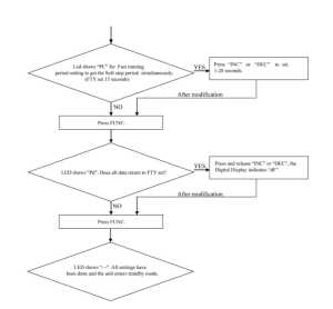
- Set the Fast Running Period (FRP) to Achieve Soft Stop Function (SPP)
When the Digital Display indicates “PC,” the Fast Running Period for opening or closing the gate is adjustable by pressing the “INC” and “DEC” buttons, respectively. The soft Stop Function is achieved simultaneously. The Soft Stop means the gate opener runs slowly during the last period before the gate completely closes.
The Soft Stop Period is unavailable for direct adjustment but is available for adjusting the Fast Running Period.
There are two running speeds designed in the program, i.e., Fast Running Speed and Soft Running Speed. The Fast Running Period is adjustable from 1 to 28 seconds. The factory default setting is 15 sec. Since the GATE OPENING OR CLOSING RUNING PERIOD (GRP) = SOFT START PERIOD(STP) +FASTRUNNING PERIOD (FRP) + SOFT STOP PERIOD (SPP), the SPP could be extended by shortening the FRP when the GRP and STP are fixed. In other words, SPP = GRP–STP–FRP. Similarly, the Soft Stop Period (SPP) can be shortened through extending the Fast Running Period(FPP).
For example, when the Soft Start Period (STP) is set at 3 sec and the GRP is 23 sec, how can we get 4 sec of Soft Stop Period (SPP) to meet the requirement? The answer is clear: We may set the Fast Running Period(FRP) at 16 sec (23 – 3 – 4 =16 sec).
- Return to Factory Set
When the Digital Display indicates “Pd,” press and release the “INC” or “DEC” button. All data will return to factory settings; the Digital Display will indicate “dF.”
- If all of the data is set and no other change is needed, press the “FUNC” Button. “- -” appears on the Digital Display, and the opener enters standby mode.
Indicate Illustration on the Digital Display When the Gate Opener is Running
The left image on the Digital Display symbolizes the motor of the gate opener 2 when the gate opener is running. The right image on the Digital Display symbolizes the motor of gate opener 1. When the motor is run to the gate-open or gate-close direction, the image on the Digital Display indicates“n” or “u” respectively. When the motor is not running, the Digital Display indicates “- -”
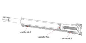
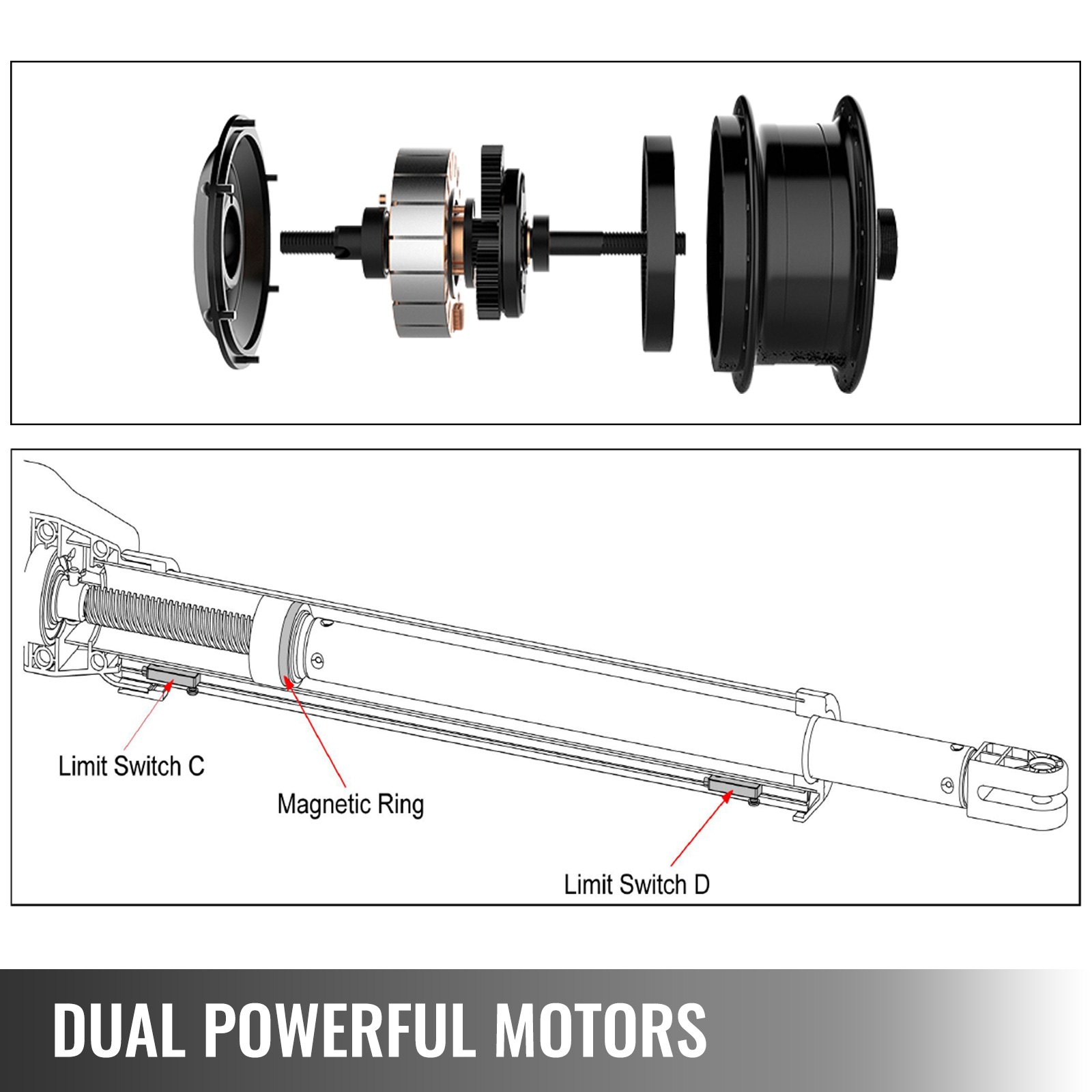
Adjusting the Limit Switch
The position of Limit Switch A was fixed in the factory; do not adjust it again. Plug on the power to running gate opener, use a screwdriver to loose the screw of Limit Switch B, slide Limit Switch B to the desired closed positionandfixit.
Limit setting for Gate 1 is finished now.
NOTE: Always place the magnetic ring between the Limit Switch A and B.
How to Operate the Dual Swing Gate Opener
The user may operate the opener once all the adjustment settings are finished.
Press and release the remote control with the gate in its closed position. The gate will move to the programmed opening position and stop.
With the gate in its open position, press and release the remote control, and the gate will move to the programmed closing position and stop.
While the gate is moving, press and release the remote control, and the gate will stop driving immediately. The next command from the remote will reverse the gate direction, and the gate will stop at its programmed opening/closing position.
The gate will stop in case of obstruction during opening. The command from the remote control will reverse the gate direction, and the gate will stop at its programmed closing position. In case of obstruction or stall force during closing, the gate will reverse and move to the programmed opening position.
NOTE: The Obstruction Sensitivity /Stall Force is adjustable in 9 levels.
Dual Swing Gate Opener Maintenance
Warning: Disconnect power before servicing.
- Wipe the gate opener shaft using a clean, dry cloth, and then apply a silicone spray to reduce its friction. In cold climates where temperatures reach 1°C (30°F) or less, spray silicone on the actuator every 4- 6 weeks to prevent up.
- Regularly check gate hinges to ensure the gate is swinging smoothly and freely. Grease hinges if needed.
- Check your installation periodically, as hardware and posts will shift. Brackets may need to be adjusted, or hardware may need to be tightened.
- Maintain the area around your gate. Keep the areas free of objects that can prevent the gate swingingfreely.
NOTES:
- Inspection and service should always be performed anytime a malfunction is observed or suspected.
- It is suggested that voltage readings be taken at the operator while at the site. Using a Digital Voltmeter, verify that the incoming voltage to the opener is within ten percent of the opener’s rating.
- Refer to Page 21 for instructions on how to check gate force and sensitivity adjustments.
Dual Swing Gate Opener Trouble Shooting
The opener does not run. The Digital Display indicator is not on.
- Check if all motors are correctly connected and color-coded. Make sure the AC input is connected.
- Check if the fuse in the control board is bad.
Opener powers up but does not run.
- The arm cable may be loose or disconnected. Verify that all wires going to the arm are secure and that the connector is properly mated to the header.
- The arm is incorrectly installed. Disconnect the motor housing from the arm and verify that the arm moves freely.
- The gate is excessively heavy, or the hinges are bad. Verify that the gate is within the ratings for this product. Disconnect the arms and verify that both gates swing easily. Lubricate or replace hinges as necessary.
- Bad control board. Call technical support for help with replacement parts.
The gate stops immediately after it starts moving.
- Obstruction sensed. Check safety devices and the gate for obstructions.
- The force is set too low. Adjust the FORCE setting until the gate completes a full open/close cycle. The force setting may need to be adjusted in cold weather, as the gate will not move freely.
- Check if the MRT period is too short.
- Incorrect power.
The gate opens but does not close.
- Photocell (PBS) is set on the control board but is not equipped (optional). Please cancel the PBS set.
- Obstruction blocking close photo eyes, Check eyes for alignment and verify all connections and operation for safety devices.
The gate ignores the limit switches.
- Check that the limit switch is not faulty.
- Check that wires to the limit switch are not shorted.
- Ensure that the motor cable is away from sources of electrical interference, such as electric fences, power lines, etc.
The gate opens, closes, or stops on its own
- Ensure that the key for manual release is in the lock position. Please refer to Step 3 of the section”Install the Gate Opener on the Gate.”
Dual Swing Gate Opener Quick-Setting Guide
Recommended For Your Project
VEVOR Dual Swing Gate Opener Heavy Duty Automatic Gate Opener Up to 880lbs & 18ft Long Gate Manual
Reviews
There are no reviews yet.