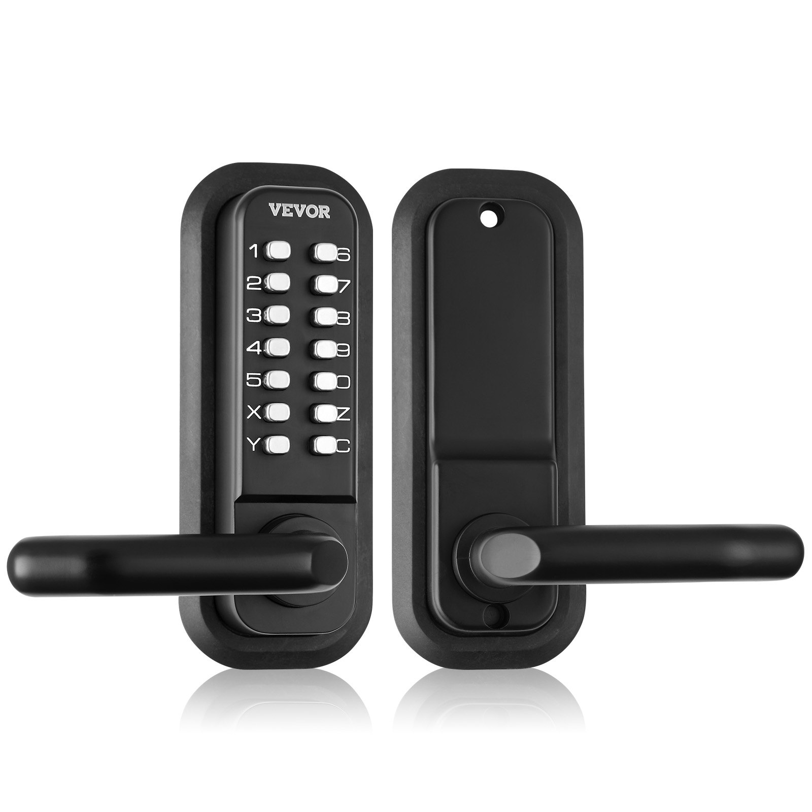
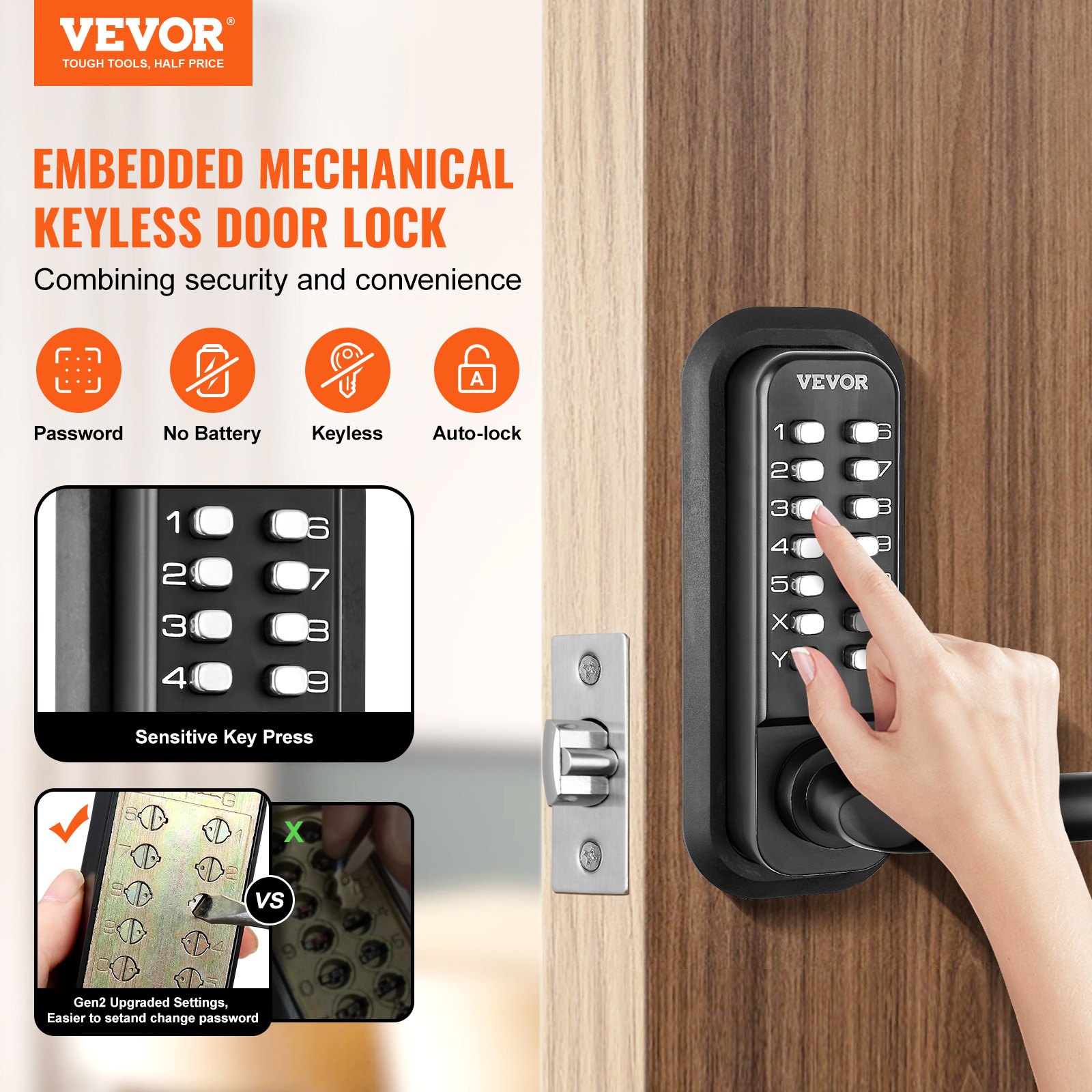
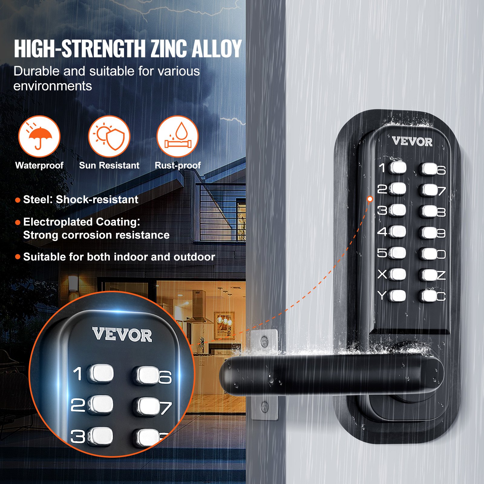
Unlock the ultimate solution for secure and convenient access with the VEVOR Mechanical Keyless Entry Door Lock. Designed with a 14-digit keypad, this embedded outdoor gate door lock set provides unmatched ease of use and reliability. Crafted from high-quality, water-proof zinc alloy, this lock is built to withstand the elements, making it perfect for gardens, garages, yards, and storage sheds.
The comprehensive manual included in the download offers step-by-step instructions for hassle-free setup, in-depth troubleshooting tips, and optimization strategies to ensure your lock operates at peak performance.
Elevate your security and enjoy the peace of mind that comes with knowing your property is protected by VEVOR’s advanced mechanical keyless entry system.
VEVOR Mechanical Keyless Entry Door Lock User Manual
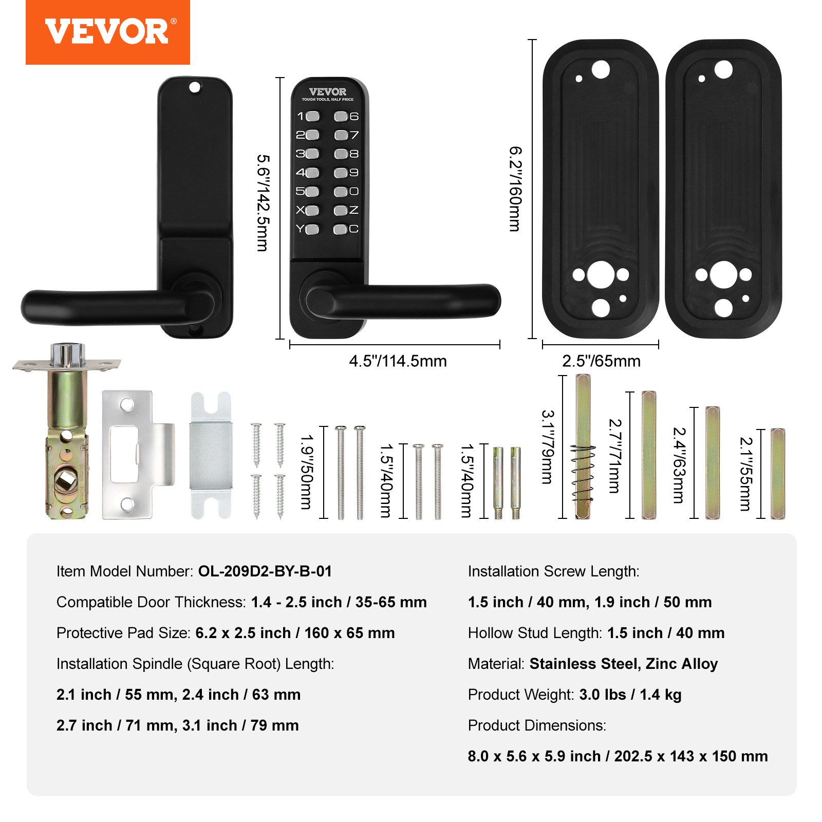
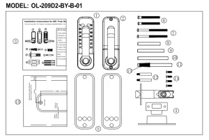
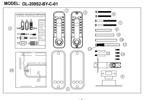
Models: OL-209D2-BY-B-01, OL-209S2-BY-C-01
Safety Instructions and Precautions
⚠️ WARNING:
Read this material before using this Mechanical Keyless Entry Door Lock. Failure to follow instructions may result in serious injury.
Assembly Precautions
-
Assemble only according to these instructions. Improper assembly can create hazards.
-
Wear ANSI-approved safety goggles and heavy-duty work gloves during assembly.
-
Keep the assembly area clean and well-lit.
-
Keep bystanders away during assembly.
Mechanical Keyless Entry Door Lock Package Contents
-
Front Panel – 1 pc
-
Back Panel – 1 pc
-
Instruction Manual – 1 pc
-
Door Striker Plate – 1 set
-
Protective Rubber Mat (160 × 65 mm) – 2 pcs
-
Screws (M4 × 40 mm) – 2 pcs
-
Screws (M4 × 50 mm) – 2 pcs
-
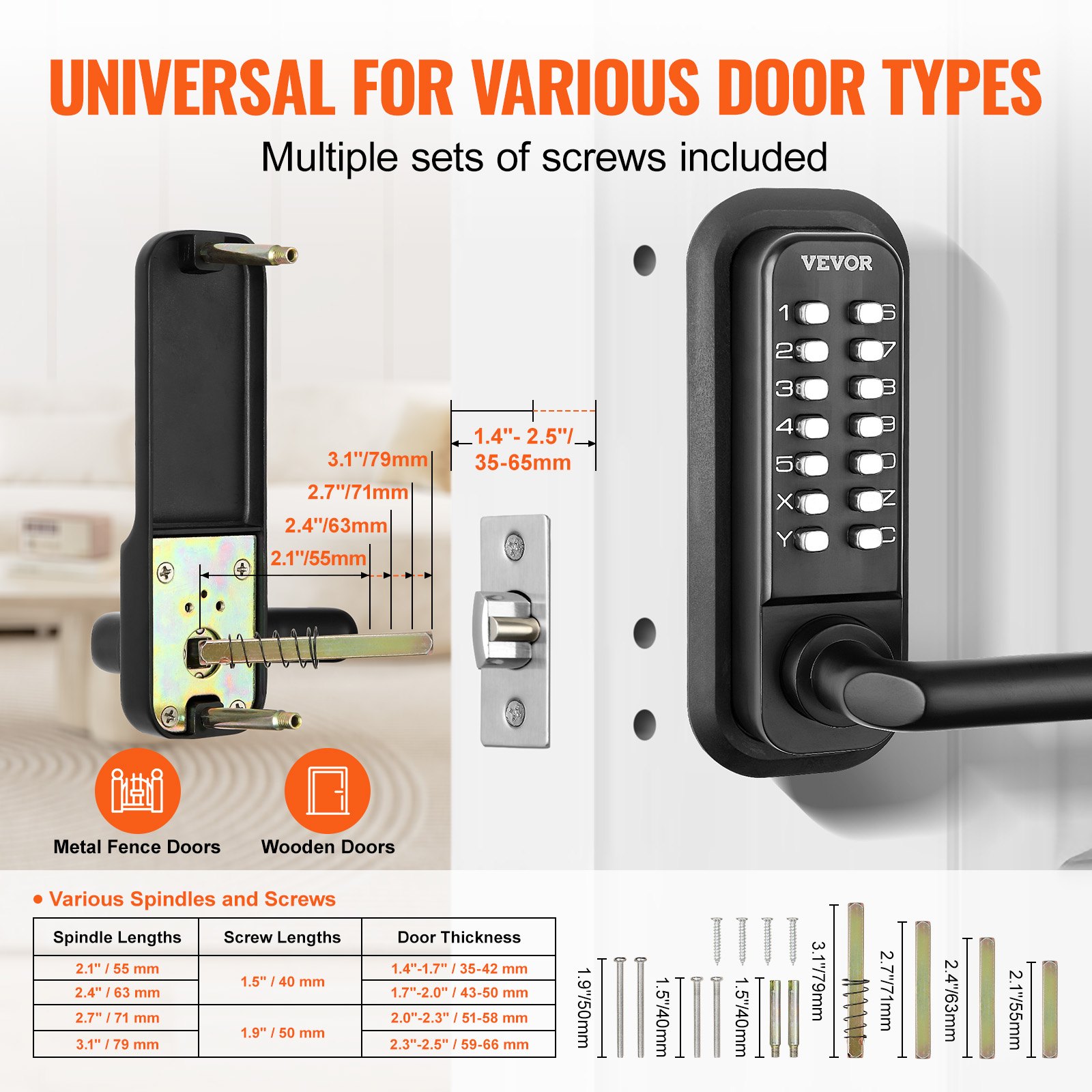
Mounting Spindle (Square, 55 mm) – 1 pc
-
Mounting Spindle (Square, 63 mm) – 1 pc
-
Mounting Spindle (Square, 71 mm) – 1 pc
-
Mounting Spindle (Square, 79 mm) – 1 pc
-
Hollow Stud (M5 × M4 × 40 mm) – 2 pcs
-
Spring – 1 pc
-
Cross-Slotted Flat Head Self-Tapping Screws (Wood Screws) – 4 pcs
-
Auxiliary Installation Drilling Sticker – 1 pc
Pre-Installation Checklist
Before installation, please:
-
Ensure all parts are working properly.
-
Set or change the password. Passwords must be set in different order and cannot be repeated. A four-digit password is the most secure.
-
Confirm that the door lock operates normally after setting the password. Check whether the lock cylinder can switch freely. You can insert the lanyards into the square hole of the feed cylinder, turn the lanyards, and verify that the lock tongue expands correctly.
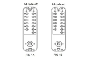
Setting or Changing the Password
-
On the back of the lock body with the number key, locate the button with the slot. When the point is directed towards the middle, the lock is in password-free mode. (See Fig. 1A)
-
To set a button as part of the password:
-
Gently push down the button with a flathead screwdriver.
-
Rotate it 180° so the point faces outward, opposite the number.
-
This indicates the button is set as a password position (G). (See Fig. 1B)
-
-
To cancel a password:
-
Hold the button with a flathead screwdriver.
-
Rotate it 180° so the point faces inward, towards the middle of the lock body (F).
-
Important:
Before installing the door, always remember the password you set
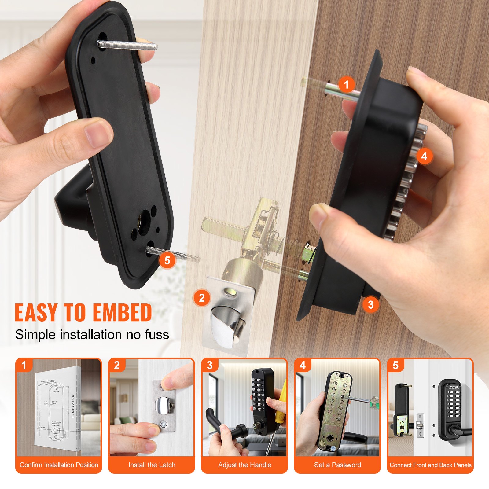
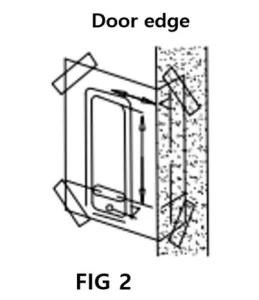
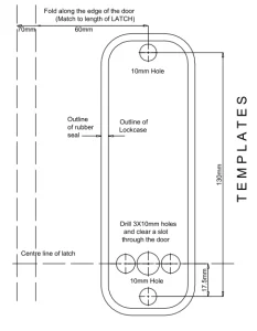
Mechanical Keyless Entry Door Lock Installation
-
Correctly position and paste the templates (see page 8) onto the inner section of the door at the required height from the ground.
-
Ensure that the marked door-to-door templates are properly aligned with the actual door-to-door position. (See Fig. 2)
-
-
Drill the marked holes:
-
Holes with a diameter of 10 mm are for the main shaft of the lanyards.
-
Holes with a diameter of 7 mm are for the bolts that secure the digital locking spindle through the fastener.
-
Holes with a diameter of 6 mm are for reinforcement pins, according to the installation template.
-
-
Drill all marked holes as indicated.
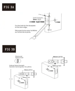
Door Edge Preparation
(Fig. 2)
Install the Lock Cylinder
-
Mark the door with the center point on the latch center line.
-
Drill a hole 25 mm in diameter and 80 mm in depth at the marked location. (See Fig. 3A)
-
Insert the lock cylinder into the drilled hole, then insert the lanyards into the square hole of the lock cylinder and tighten securely.
-
Drill a small 3 mm hole in the mounting hole of the lock cylinder.
-
Secure the lock cylinder with wood screws to ensure proper positioning.
-
Adjust the size according to the lock cylinder specifications (see Fig. 3B):
-
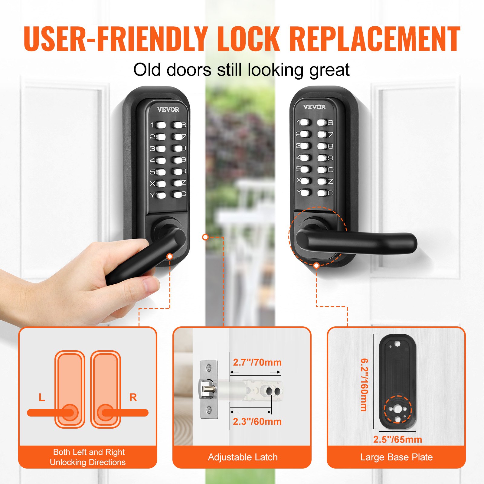
Push forward = 60 mm
-
Pull back = 70 mm
-
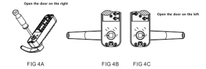
Handle Adjustment
-
After opening the package, locate the handle above the lock body. Confirm the correct direction of the handle before adjusting (left-opening or right-opening door).
-
Using a Phillips screwdriver, loosen the bolt on the lock body and remove the handle. (See Fig. 4A)
-
Adjust the handle to the desired door-opening direction (left or right), then securely tighten the bolts. (See Fig. 4B/C)
-
Insert the lanyards into the lanyard hole and turn the stem until the triangular arrow on the lanyard sleeve aligns with the handle.
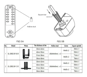
Square Bar Positioning
-
Screw the hollow stud into the screw holes of the front panel of the door lock. (See Fig. 5A)
-
Based on the thickness of the door, select the appropriate drive shaft and mounting screws.
-
The default bar size is 8 x 8 mm, designed for doors with a thickness of 35–65 mm. If necessary, cut the square bar to fit the door thickness.
-
Insert one end of the bar (with spring) into the square hole of the lock body, and the other end into the corresponding square hole of the rear handle body. Secure in place. (See Fig. 5B)
Important: Do not close the door until you have confirmed that the password and lock function properly.
-
If necessary, shorten the bolts to match the thickness of the door.
-
When shortening, ensure at least 4–5 threads remain engaged in the lock box.
-
Position the rubber seal behind the mechanical combination lock, then secure the lock using fixing bolts at both the neck and bottom.
-
Before fully tightening, confirm that the lock is vertically aligned. Test the lock and latch function to ensure smooth movement.
-
Do not overtighten the bolts or seals, as this may damage the mechanism and affect proper operation.
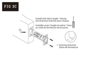
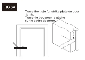
Doorframe Striker Plate Installation
-
Important Note: Ensure the striker plate is positioned so the lock latches can enter the hole. The safety bolt of the lock should not enter the striker plate hole.
-
Based on this requirement, place the striker plate on the doorframe in the proper position.
-
Once the location is correct, mark around the striker plate and mark the positions of the two screw holes.
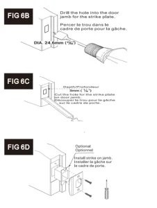
-
Remove the striker plate, align the box with the marked holes, mark around the box, and remove it.
-
Cut out a square hole in the frame to match the box dimensions—approximately 24.6 mm deep (FIG 6B). This will allow the box to fit securely.
-
Create an additional 3 mm deep square recess so that the striker plate sits flush with the doorframe (FIG 6C).
Normally Open Mode – Setting and Cancellation
-
To set Normally Open Mode:
-
Press and hold the handle and the Y key simultaneously.
-
Enter the correct password.
-
After entering, release the handle first, then release the Y key.
-
The lock is now in Normal Open Mode.
-
-
To cancel Normally Open Mode:
-
Press and hold the C key.
-
While holding, press the handle.
-
The lock will exit Normally Open Mode.
-
Recommended For Your Project
VEVOR Mechanical Keyless Entry Door Lock, 14 Digit Keypad Manual
Reviews
There are no reviews yet.