Unlock the full potential of your VEVOR Split Charge Relay Kit with our comprehensive product manual. Our 6mtr 12V Automatic Dual Battery Isolator Kit with a 140AMP Voltage Sense Relay (VSR) is designed for seamless integration into your RV, marine vehicle, car, truck, caravan, camper, yacht, ATV, UTV, or workshop.
This manual provides step-by-step instructions to simplify the setup process and ensure optimal performance of your dual battery system. Whether a seasoned professional or a DIY enthusiast, you’ll find value in our guide’s detailed troubleshooting tips, setup procedures, and optimization techniques.
The VEVOR Split Charge Relay Kit manual is your go-to resource for maintaining battery health, extending battery life, and preventing power dropouts. Download now to experience hassle-free installation and enhanced reliability for all your power needs.
Dual Battery Kit Fitting Instructions
We recommend that the Split Charge Relay Kit be installed by a licensed auto-electrician.
WARNING:
- Like any addition to your 12V set-up, ensure you’ve installed a fuse or circuit breaker at each battery
- Ensure the dual battery kit is out of the way of moving parts and sharp objects, which could ruin the integrity of any component of the split charge relay kit.
- Ensure all connections are secure and there is no loose or exposed wiring
- Check regularly for signs of stress or damage
- DO NOT USE the kit if it has sustained any damage.
Tools Required
- Cutting pliers, sidecutters or a cable stripper to cut and strip the cable
- Crimpers for terminal crimping
- Spanner set or socket set
- Philips screwdriver
- Power drill and 3.5mm(9/64)drill bit
- Voltmeter
Dual Battery Kit Fitting Instruction
STEP 1:
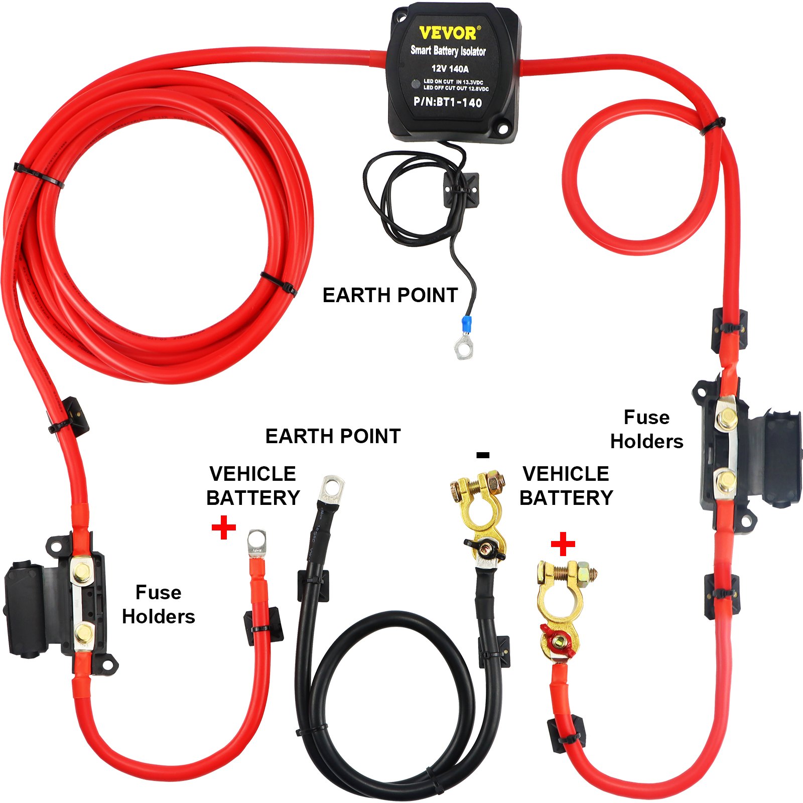
Lay out your Dual Battery Kit and check that all the components are in the kit. Supplied should be:
- 12 Volt 140 Amp HC Cargo Voltage Sensing Split Charge Relay
- 2 x 250mm red 110 amp cables
- Starter and leisure battery for fuse box leads.
- 1 x 500mm red 110 amp cable fuse box to relay leads
- 1 x (1,3,4,5 )mtr red 110amp cable relay to fuse box lead
- 1 x 1 mtr 110 amp black ground cable. Positive and Negative 8mm Post Battery Terminals
- 2 X fuse holder and 100A fuse, spare parts included.
- 15 x Cable Ties + Fixtures to keep everything neat and tidy.
- 2 mtr split conduit to protect cables in the engine compartment.
STEP 2:
Isolate the starting battery by removing the negative terminal.
STEP 3:
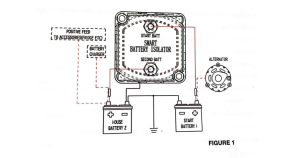
Select a location for the Smart Battery Isolator (SBI) that is easily accessible, does not have the cables running near your exhaust, and is as close as possible to the starting battery.
STEP 4:
Remove the lower mounting plate from the SBI as a template and mark the position of the four (4)holes to be drilled. Drill the holes using a 3.5mm (9/64) drill bit.
STEP 5:
Secure the two (2) blind holes of the base with the short 4mm screws.
Split Charge Relay Kit Fitting Instructions
STEP 6:
Take the 6-meter length of red cable, which has been terminated at both ends. Begin from the center of the mounting plate and run the cable along the inner guard and firewall to the positive terminal of the starting battery (be careful to keep the wiring away from any moving parts). Cut the cable to length.
STEP 7:
Repeat the above process at the positive terminal of the auxiliary battery.
STEP 8:
Strip the unterminated ends of both cables back 15mm, fit the copper lugs, and crimp in place, making sure the connection is secure. Alternatively, you can solder the cable to the lug if you wish.
STEP 9:
Slide the heat shrink over the lug and cable, then heat with a flame or hairdryer until secure.
STEP 10:
Attach the insulated ring terminal to the black wire on the SBI. This is an earth wire, and it must have a secure and clean (bare metal) contact. If possible, select a nearby bolt or screw that is earthed to the body.
Dual Battery Kit Fitting Instructions
STEP 11:
Attach both red cables to the SBI and tighten the retaining nuts. The cable from the start battery goes to the stud on the SBI with the painted RED dot. The cable from the auxiliary battery goes to the unpainted stud.
NOTE: YOU MUST CUT THE NOTCHED SECTIONS IN THE SBI HOUSING WHERE YOU REQUIRE THE CABLE TO EXIT.
STEP 12:
Mount the SBI to the bottom plate and fix with the two (2) longer 4mm screws.
STEP 13:
Secure the black earth lead on the SBI to the selected earth point.
STEP 14:
Fit the Positive (Red +) battery terminal and the Negative (Black -) battery terminal to the auxiliary battery and tighten.
STEP 15:
Auxiliary battery BLACK earth cable: Select a nearby body bolt or drill an 8mm hole in the inner guard and secure one end of the black earth cable. Make sure to have a secure and clean (bare metal) connection.
WARNING: LIKE ANY ADDITION TO YOUR 12V SET-UP, ENSURE YOU’VE INSTALLED A FUSE OR CIRCUIT BREAKER AT EACH BATTERY
STEP 16:
Attach the RED lead from the SBI to the auxiliary battery’s positive (+) terminal and tighten, then secure the cable using the cable ties.
STEP 17:
Attach the other end of the BLACK earth to the auxiliary battery’s negative (-) terminal.
STEP 18:
Before fitting the battery terminal to the positive side of the start battery, check the type of the existing battery terminal and if it has a stud and nut on the terminal to secure the existing wiring, connect to the existing terminal.
Split Charge Relay Kit Fitting Instructions
STEP 19:
Attach the RED cable from the SBI to the positive (+) terminal of the start battery and tighten, secure the cable using the cable ties.
STEP 20:
Re-connect the start battery earth cable.
STEP 21:
Test for a proper earth on the auxiliary battery by placing a voltmeter across the positive (+) and negative (-)terminals and taking a reading. Remove the negative (-) probe and put it on an earth point on the body or engine(not the point where the earth cable is mounted); both readings should be the same. If the readings differ, ensure the earth cable has a clean and secure mounting.
STEP 22:
Start the vehicle’s engine.
STEP 23:
When the starting battery’s voltage reaches the cut-in voltage, the relay closes automatically, allowing the auxiliary battery to be charged. This is indicated by the illuminated red light on the front panel of the SBI.
STEP 24:
Ensure that the auxiliary battery is charging by checking the voltage above 13.3V.
STEP 25:
Turn off the engine.
STEP 26:
Check that the SBI disengages when the start battery’s voltage falls below the cut-out voltage. This can take some time, so to speed up the process, turn on the headlights or leave the door open and interior lights on. If the SBI works per the above tests, congratulations, you have successfully installed your split charge relay kit.
Recommended For Your Project
VEVOR Split Charge Relay Kit, 6mtr 12V, Automatic Dual Battery Isolator Kit Manual

Reviews
There are no reviews yet.