

Unlock the full potential of your VEVOR Bathroom Exhaust Fan with our comprehensive product manual download. This manual is designed with user convenience at its core, providing detailed step-by-step instructions to ensure effortless setup, optimal performance, and effective troubleshooting.
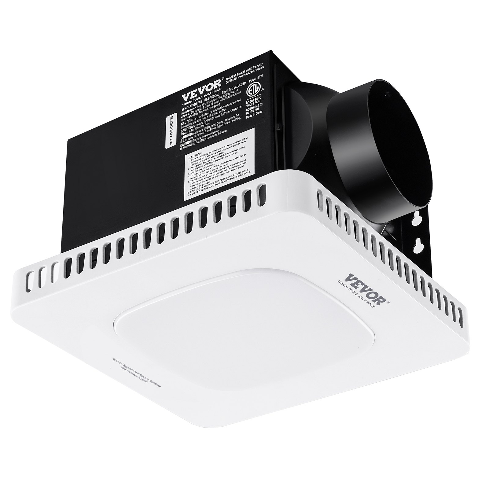
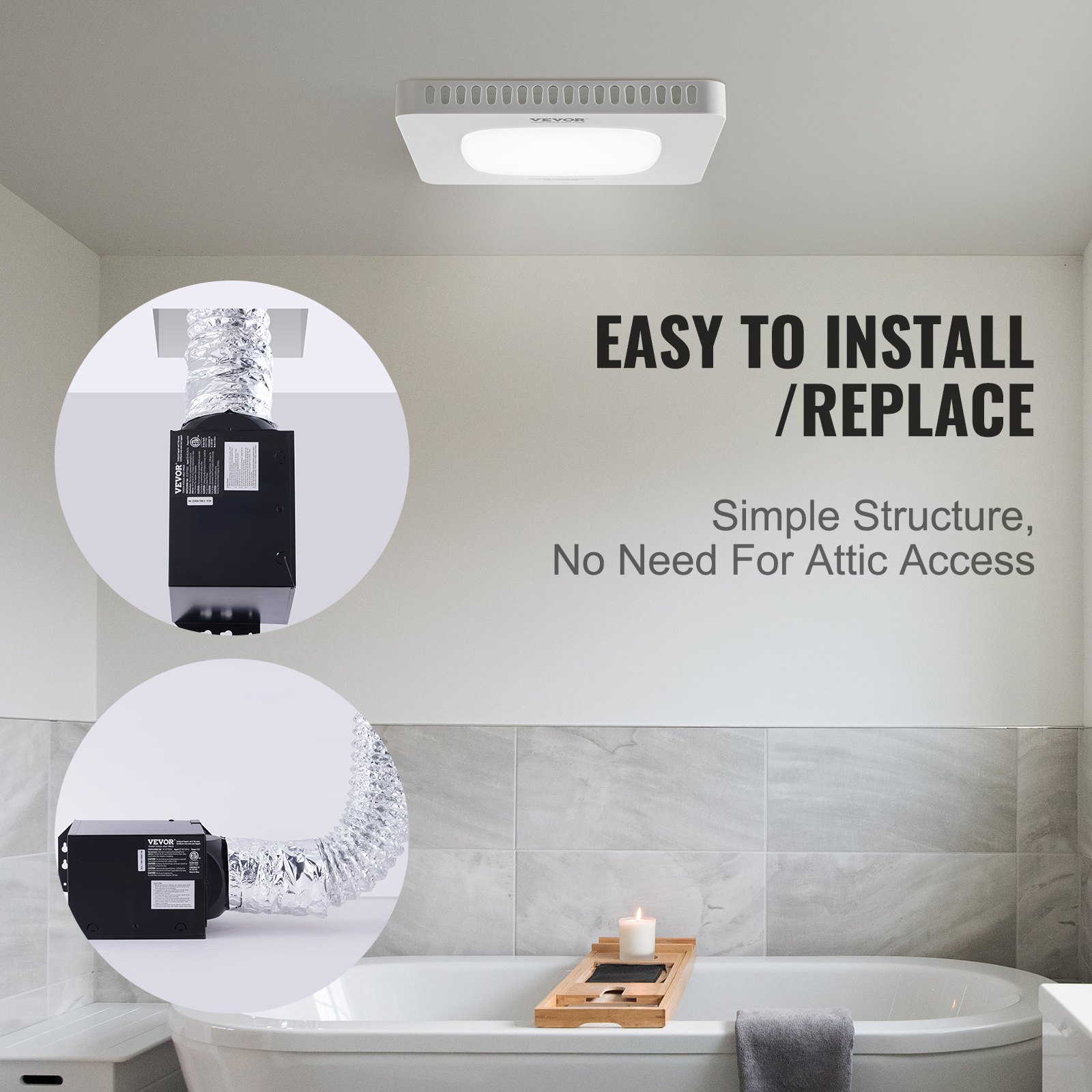
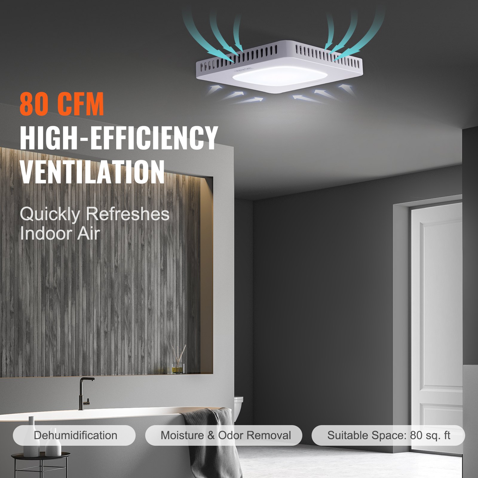
Whether you’re installing the 80 CFM High-Efficiency Ventilation system or managing the 1.5 sones low noise operation of the all-copper motor, this guide has you covered. Energy-saving tips and maintenance advice are also included to help you maximize the efficiency and lifespan of your bathroom ceiling fan, without the need for attic access.
Perfect for various ceilings, our manual ensures you get the most out of your VEVOR Bathroom Exhaust Fan.
This is the original instruction. Please read all manual instructions carefully before operating. VEVOR reserves the right to interpret our user manual. The appearance of the product shall be subject to the product you received. Please forgive us for not informing you again if there are any technology or software updates on our product.
READ & SAVE THESE INSTRUCTIONS
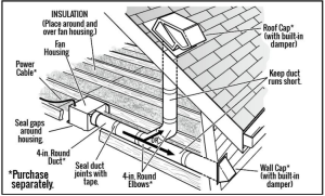
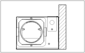
Bathroom Exhaust Fan Typical Installation
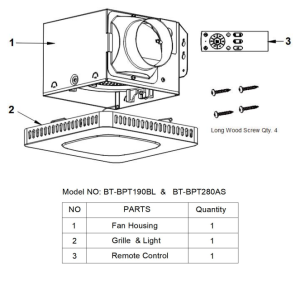
PACKAGE CONTENTS
SAFETY INFORMATION
Please read and understand this manual before assembling, operating, or installing the product.
WARNING
To Reduce The Risk Of Fire Or Electric Shock. Do Not Use This Fan With a Solid-State Speed Control Device. Include instructions about the risk of fire, electric shock, or injury to persons, as well as cleaning and user maintenance, such as lubrication.
DO NOT operate any fan with a damaged cord or plug. Discard the fan or return to an authorized service facility for examination and/ or repair.
DO NOT run cord under carpeting. Do not cover the cord with throw rugs, runners, or similar coverings.
DON’T route cord under furniture or appliances. Arrange the cord away from the traffic area and where it will not be tripped over. Disconnect the appliance from the power supply before servicing.
Regular Check: Have your wall fan checked regularly for any sign of malfunction! Stop using. Check if the plug, cord, or appliance is damaged. Excessive noise, unpleasant odor, or abnormal heat.
This appliance is not intended for use by people(including children)with reduced physical, sensory, or mental capabilities, or a lack of experience and knowledge, unless they have been given supervision or instruction concerning the use of the appliance by a person responsible for their safety.
Children should be supervised to ensure they do not play with the appliance.
Close supervision is necessary when any appliance is used by or near children. Children should be supervised to ensure that they do not play with appliances. Cleaning and user maintenance shall not be done by children unless they are older than and supervised.
Use the appliance only for intended household purposes as described in this User Manual. Any other use is not recommended, as it may cause fire, electric shock, or injury to people.
The duct fan shall not be intended to be mounted in a duct to move heated air.
Other safety rules
- Always disconnect the power supply before servicing the fan, motor, or junction box.
- Installation work must be performed by a qualified person(s) per local and safety codes, including the rules for fire-rated construction.
- Follow all local building, safety, and electrical codes, as well as NEC ( National Electrical Code) and OSHA (Occupational Safety and Health Act).
- Electric service supply must be 120 volts, 60 hertz.
- This unit must be properly grounded.
- Do not bend or kink the power wires.
- Exercise care not to damage existing wiring when cutting or drilling into walls or ceilings.
- Sufficient air supply is required for proper combustion and the exhaustion of gases through the chimney(flue) of fuel-burning equipment to prevent back-drafting. See the standards of NFPA( National Fire Protection Association) and ASHRAE (American Society for Heating, Refrigerating, and Air Conditioning Engineers) and the local building code authorities.
- Do not use this fan with any solid-state control device, such as a remote control, dimmer switch, or certain timers. Mechanical timers are not solid-state devices.
- This ventilation fan is approved for use over a bathtub or shower when installed in a GFCI-protected circuit. Do not use fans over a bathtub or shower that are not approved for that application and marked accordingly.
- Do not install in a cooking area.
- Do not use it to exhaust hazardous or explosive vapors.
- Fans should always be vented to the exterior and in compliance with local codes.
- Do not install in a ceiling with insulation greater than R50.
- Ductwork should be installed straight with minimal bends.
- Duct work size must be the same size as the discharge and should not be reduced. Reducing the duct size may increase fan noise.
- Before servicing or cleaning this unit, shut off pthe ower supply at the panel and lock to prevent the power from being turned on. If the panel cannot be closed, clearly mark the panel with a warning tag to prevent the power from being turned on.
- Use this unit in the manner intended by the manufacturer. If you have any questions, please call customer service.
READ AND SAVE THESE INSTRUCTIONS
PREPARATION
Before beginning the product assembly, make sure all parts are present. Compare parts with the package contents list and the hardware contents. Do not attempt to assemble the product if any part is missing or damaged.
Estimated Assembly Time: 30 minutes
Tools Required for Assembly (not included): Hammer, FlatheadScrewdriver, Wood Screws, Duct Tape Philips Screwdriver, Utility Knife
Helpful Tools (not included): Electric Drill, Drill Bits.
WARNING: Turn off the electricity at the breaker box before beginning installation.
Carefully remove the unit from the carton. Check the area above the installation location to ensure that wiring can run to the planned location, that ductwork can be run, and that the area is sufficient for proper ventilation.
Inspect ductwork and wiring before proceeding with installation. Before installation, provide inspection and future maintenance access to a location that will not interfere with installation work. You may need the help of a second person to install this fan: one person on the attic side and one on the room side.
Note: Installations may vary depending on how the previous bath fan was installed. Supplies necessary for installing your bath fan are not all included; however, most are available at your local home improvement or hardware store.
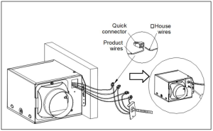
Bathroom Exhaust Fan Wiring Diagram
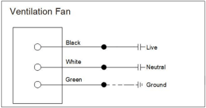
WARNING: COPPER TO COPPER ONLY. Do not use aluminum wire.
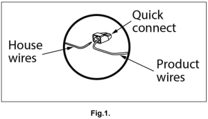
CAUTION: The Accessory part (quick connector) should meet the installation instructions below.
NOTE: The connector is reusable on solid wires of the same gauge or smaller. Do not reuse the connector on stranded cables.
- Strip wires 3/8 in. – 1/2 in.
- Grip the wire firmly and push the stripped end of the wire into the open port of the connector. Use only one connector per port.
- Verify that the stripped ends of the wires are fully inserted into the back of the connector. (See Fig.1.)
NOTE: Important wire information. Maximum temperature rating 221˚F(105˚C). 600 volts maximum for building wire and 1,000 volts maximum for building wire and 1,000 volts maximum in signs and lighting fixtures.
The acceptable wire range includes: Solid: 12-18 AWG.
Bathroom Exhaust Fan Installation Instructions
Review all safety precautions. Ensure the electricity at the breaker box is turned off before installation.
1. Choose the location for your fan on the ceiling. Use the shortest possible duct run and a minimum number of elbows for the best possible performance. Then, cut an opening that measures 7.68in. x7.6in.

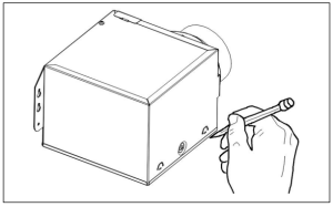
NOTE: You can also use a pen to mark the fan housing and cut holes according to the marked size.
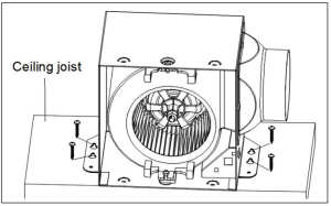
2. Place the fan housing next to a ceiling joist or wall stud. The fan housing should be level and perpendicular to the ceiling joist or wall stud.
3. Mount the fan housing to the ceiling joist or wall stud using the wood screws (included) where indicated.
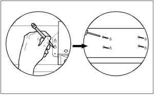
NOTE: You can use a pen to mark the keyhole slot on both mounting brackets. Screw in the wood screws using the marked positions. Reserve a 3-5mm length for the screw head. Then hang the fan onto the mounting plate and tighten the screws.
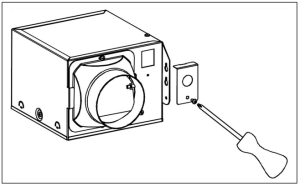
4. Remove wiring box cover from fan housing with Phillips screwdriver (not included).
5. Use a quick connector to secure the 120 VAC house wiring from the wall switch to the fan. 14 AWG is the minimum wire used for branch circuit wiring. Carefully push the connected wires back into the wiring box housing. Reattach the wiring box cover.
CAUTION: If the electrical wires do not match the colors listed, you must determine what each house wire represents before connecting. You may need to consult an electrical contractor to decide whether or not it is safe.
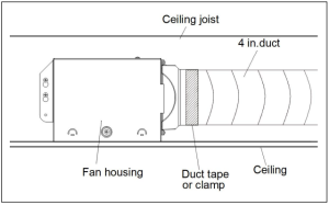
6. Install a circular 4 in. duct (not included) and secure it with duct tape or clamps (neither included). Finish ceiling work. The ceiling should be aligned with the edge of the fan housing.
7. Carefully connect the light wires.
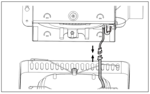
NOTE: The Model NO: BT-BPT280AS also has a colored light power cable; please be careful to connect it simultaneously.
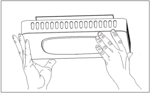
8. Pinch mounting springs on grille and insert into narrow rectangular slots inside the fan housing. Push the grille up toward the ceiling.
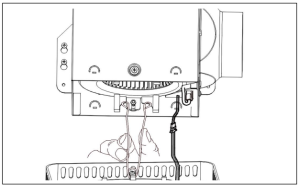
9. Push grille against the ceiling—complete installation.
Bathroom Exhaust Fan Remote Control Instructions
1. Match code:
Holding the Match code button within 5 seconds after one sound of power on, until you hear Didi twice successfully match the code.
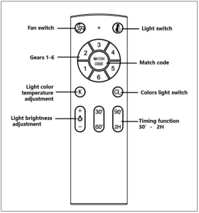
2. Light switch:
When the wall control switch is turned on, the default light is on, and the light is on: neutral light;
3. Light color temperature adjustment:
When you turn the light on, use the “Light color temperature adjustment” button to adjust the color temperature.
3.1. Use the “+” button on the “Light color temperature Adjustment” button to increase the color temperature;
3.2. Use the “-” button on the “Light color temperature Adjustment” button to reduce the color temperature;
4. Light brightness adjustment:
Turn on the light and use the “Brightness adjustment” button to adjust the brightness when the light is on;
4.1. Use the “+” button on the “Brightness adjustment” button to increase brightness;
4.2. Use the “-” button on the “Brightness adjustment” button to reduce brightness;
5. Timing function:
5.1. Timing: 30 minutes, 60 minutes, 90 minutes, 2 hours.
6. Fan Switch:
If the fan runs, you can select gears 1-6. If the fan is in the shutdown state, press the “ Fan switch ” button, and the fan will start running. You can choose your gears according to your needs.
7. Colors Light Switch:
Model NO: BT-BPT280AS with color lighting function; The colored light function is disabled by default. Press the “ Colors light switch” button to turn on the colored light, and continuously press the“ Colorslightswitch ” button to have 7 colors that can be cycled.
NOTE: Model NO: BT-BPT280BL does not have a color lighting function; pressing the “ Colors light switch ” button will not have any function.
CARE AND MAINTENANCE
WARNING: Disconnect the power supply before servicing.
See SAFETY INFORMATION before proceeding. Routine maintenance should be done at least once a year.
- Wash grille with mild soap and water, dry with a cloth.
- Remove excess dirt and dust from the fan housing with a vacuum cleaner.
- Do not use solvents, thinners, or harsh chemicals to clean the fan.
- Do not allow water to enter the motor.
- Do not immerse resin parts in water over 60ºC.
Bathroom Exhaust Fan Troubleshooting
Q: Excessive noise
A: 1. It is normal that there is noise during operation. Turn the fan down to a lower speed if it’s too loud.
2. Check if the blade is installed correctly.
Q: The Fan does not operate
A: 1. Ensure the fan is connected to a powered electrical outlet.
2. Clean the blade regularly.
Made In China.
Recommended For Your Project
VEVOR Bathroom Exhaust Fan, 80 CFM High-Efficiency Ventilation, 1.5sones Manual
Reviews
There are no reviews yet.