Unlock the full potential of your solar energy system with our VEVOR 40A MPPT Solar Charge Controller. This comprehensive product manual is designed to guide you through every step of setup, optimization, and troubleshooting for your 12V or 24V auto DC input solar panel regulator charger.
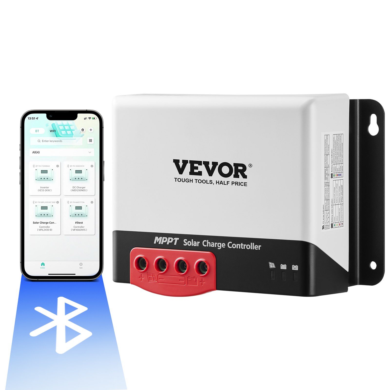
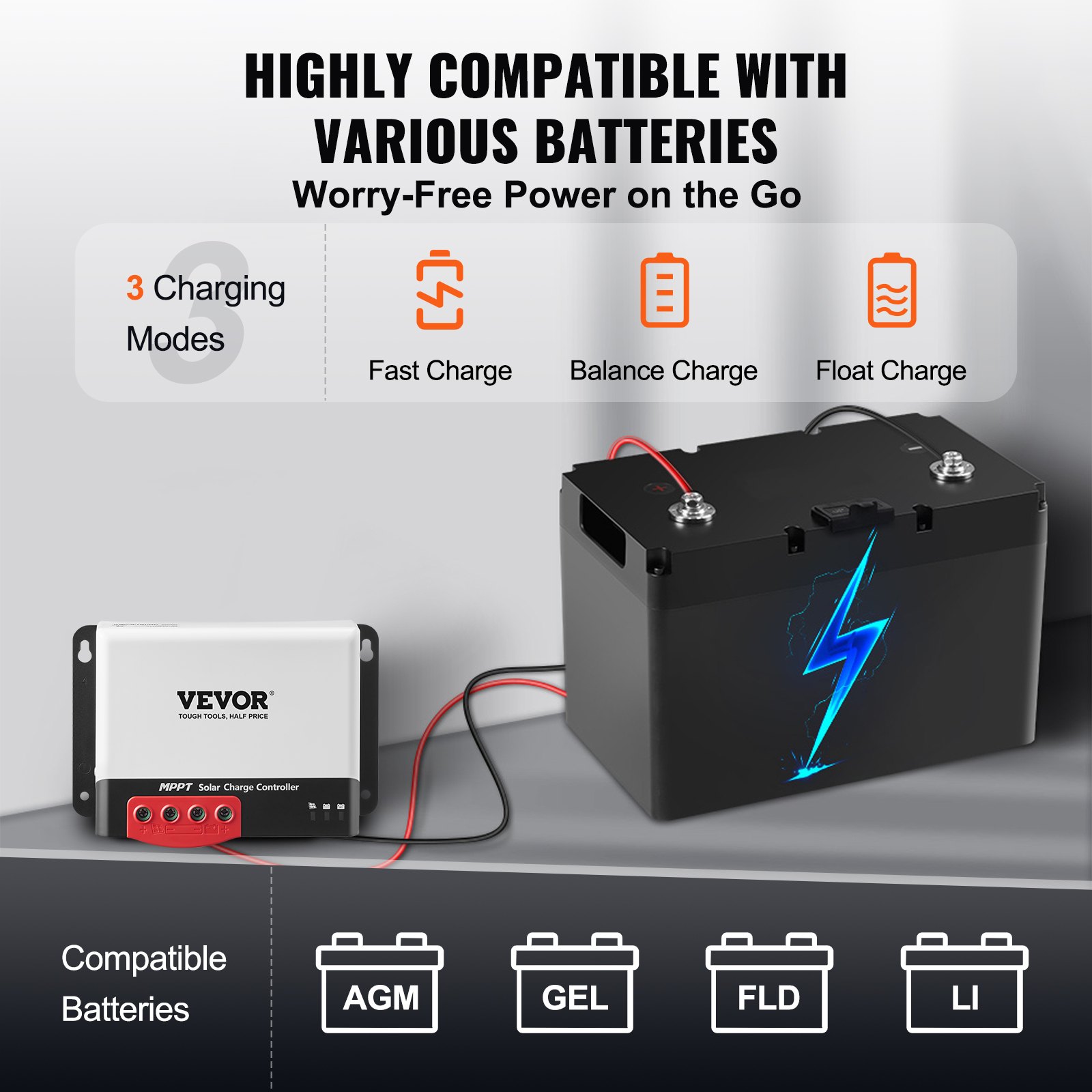
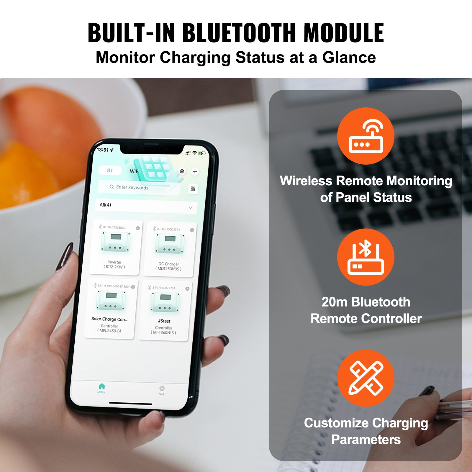
Featuring 98% charging efficiency and compatibility with sealed (AGM), gel, flooded, and lithium batteries, this manual ensures you get the most out of your solar power investment. With the included Bluetooth module, monitor and control your system effortlessly from your mobile device.
Our manual is user-friendly, detailed, and essential for beginners and seasoned solar enthusiasts. Download now to maximize your solar charging efficiency and maintain peak performance.
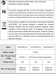
MODEL: MC2430N10-B/ MC2440N10-B/ MC2450N10-B
SAFETY INSTRUCTIONS
- The applicable voltage of the controller exceeds the safety voltage for the human body, so please read the manual carefully before use and operate the controller only after safety operation training has been completed.
- No parts inside the controller need to be maintained or repaired. The user shall not disassemble or repair the controller.
- Install the solar charge controller indoors to prevent component exposure and water from getting in.
- Please install the controller in a well-ventilated place to prevent the heatsink from overheating.
- Installing a proper fuse or circuit breaker outside the controller is recommended.
- Be sure to disconnect the PV array’s wiring and the fuse or circuit breaker near the battery terminal before installing and adjusting the controller’s wiring.
- Check that all wiring is tight after installation to avoid the danger of heat accumulation due to poor connections.
1. INTRODUCTION
1.1 Overview
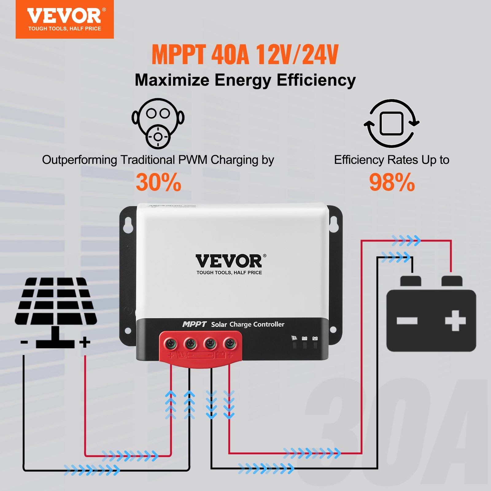
- With industry-leading PowerCatcher MPPT technology, the MC solar charge controller enables maximum energy tracking for solar panels. This technology allows the controller to quickly and accurately track the maximum power point of PV array in any environment, obtain the maximum energy of solar panels in real time, and significantly increase energy utilization efficiency of the solar energy system.
- This product can be connected to an external LCD screen or Bluetooth communication module and PC Upper Computer for dynamic display of operating status, operating parameters, controller logs, control parameters, etc. The user can look up various parameters and modify the control parameters to suit different system requirements.
- The controller adopts a standard Modbus communication protocol, which makes it convenient for the user to view and modify the system’s parameters. Meanwhile, the company provides free monitoring software that can maximize users’ convenience and meet different needs for remote monitoring.
- The controller provides an overall electronic fault self-test and powerful electronic protection functions that minimize component damage due to installation errors and system failure.
1.2 Solar Charge Controller Features
- PowerCatcher’s maximum power point tracking technology allows the controller to track the maximum power point of solar panels even in a complex environment. Compared with traditional MPPT tracking technology, it boasts faster response speed and higher tracking efficiency.
- A built-in maximum power point tracking (MPPT) algorithm can significantly increase the energy utilization efficiency of the photovoltaic system, which is about 15% to 20% higher than traditional PWM charging.
- It provides an active charging voltage regulation feature. At battery open circuit or lithium battery BMS overcharge protection, the controller battery terminal will output the rated charging voltage value.
- MPPT tracking efficiency is up to 99.9%.
- Due to advanced digital power technology, the circuit energy conversion efficiency is as high as 98%.
- It is available in multiple battery types and supports charging procedures for various types of batteries, such as lithium, colloidal, sealed, and vented batteries.
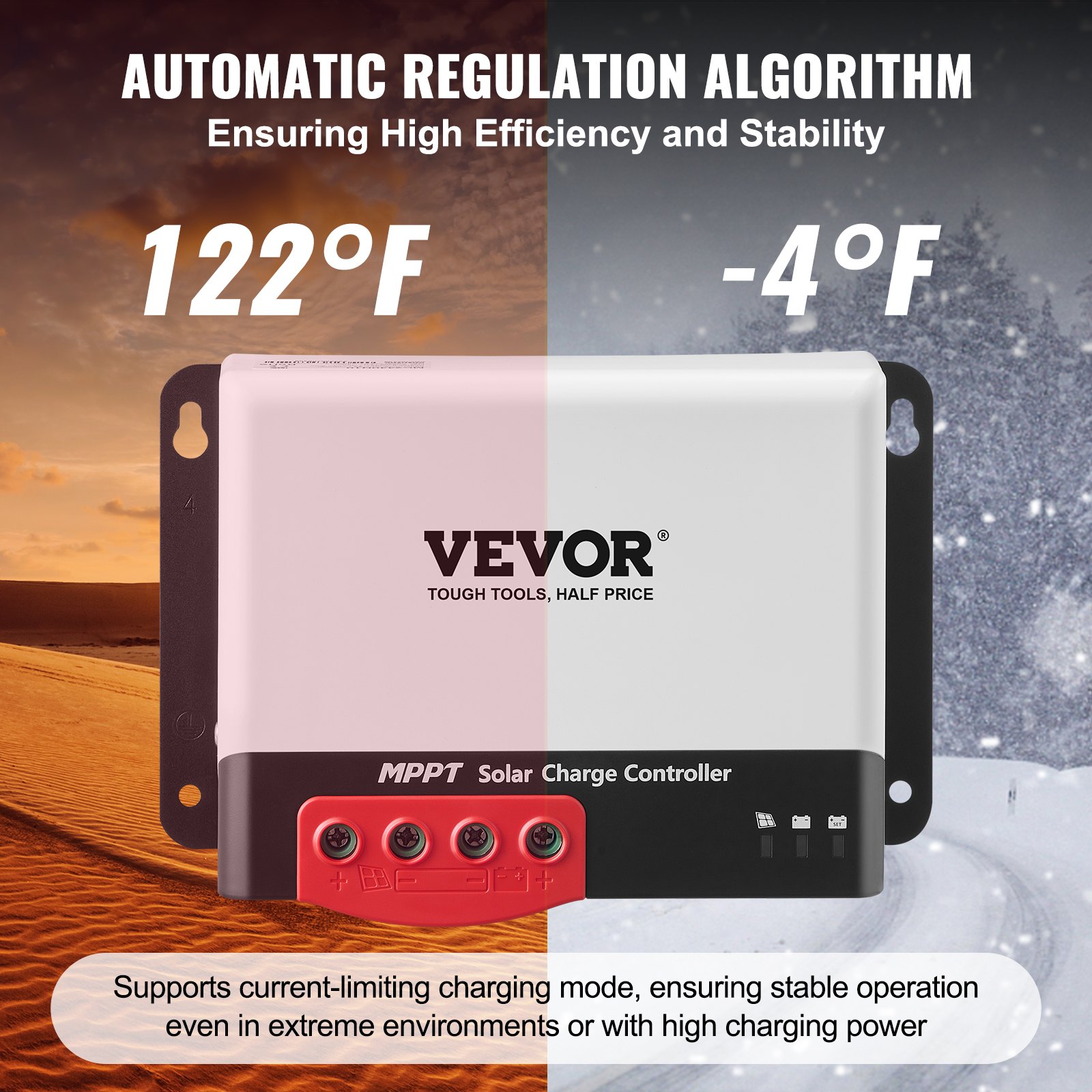
- A current-limited charging mode is available. When the solar panel’s power is too large and the charging current is higher than the rated value, the controller automatically reduces the charging power so that the solar panel can operate at the rated charging current.
- Support automatic identification of lead-acid battery voltage.
- Connect an external LCD screen or Bluetooth module to view equipment operating data and status, and modification of controller parameters is supported.
- Optional built-in Bluetooth function: Helps view the running data and status of equipment, and support the change of controller parameters.
- An optional built-in CAN function can view the running data and equipment status and support the change of controller parameters.
- Support standard Modbus protocol to meet communication needs on different occasions.
- A built-in over-temperature protection mechanism ensures that when the temperature exceeds the device’s set value, the charging current decreases linearly, thereby reducing the controller’s temperature rise and avoiding high-temperature damage.
- Temperature compensation and automatic charge and discharge parameter adjustment help improve battery life.
- Solar panel short circuit protection, battery open circuit protection, TVS lightning protection, etc.
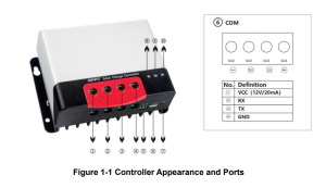
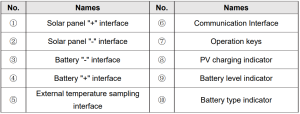
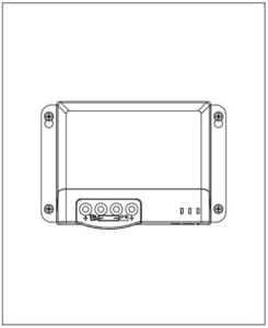
1.3 Appearance
1.4 MPPT Technology Introduction
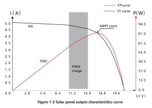
The Maximum Power Point Tracking (MPPT for short) system is an advanced charging technology that enables the solar panel to output more energy by adjusting the operating conditions of the electrical module. Due to the non-linear characteristics of solar arrays, there is a maximum energy output point (maximum power point) on an array’s curve.
Traditional controllers (switch charging technology and PWM charging technology) fail to maintain battery charging at this point; therefore, the solar panel’s maximum energy cannot be obtained.
However, the solar charge controller with MPPT control technology can track the array’s maximum power point at all times to obtain the maximum energy to charge the battery. Take a 12V system as an example. The solar panel’s peak voltage (Vpp) is about 17V, while the battery voltage is about 12V.
Generally, when the controller is charging the battery, the solar panel’s voltage is about 12V and does not fully contribute to its maximum power. But the MPPT controller can overcome this problem. It constantly adjusts the solar panel’s input voltage and current to achieve the maximum input power.
Compared to the traditional PWM controller, the MPPT controller can provide the solar panel’s maximum power and thus a larger charging current. The MPPT controller can generally improve energy utilization by 15% to 20% compared with the PWM controller.
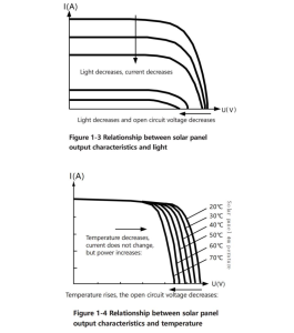
In addition, due to the difference in ambient temperature and light conditions, the maximum power point often changes. The MPPT controller can adjust parameters according to different conditions from time to time to keep the system near its maximum working point. The whole process is fully automatic and does not require any user adjustments.
1.5 Charging Stage Introductions
MPPT cannot be used alone as one of the charging stages. To complete the battery charging process, it is usually required to combine boost charge, floating charge, equalizing charge, and other charging methods. A complete charging process includes Quick, holding, and floating charges.
The charging curve is shown below:
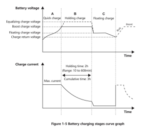
a) Quick charge
In the quick charge stage, the battery voltage has not yet reached the set value of full charge voltage (i.e. equalizing/boost charge voltage), so the controller will perform MPPT charging, which will provide maximum solar energy to charge the battery, when the battery voltage reaches the pre-set value, constant voltage charge will start.
b) Holding charge
The controller will charge the battery constantly when it reaches the set holding voltage value. This process will no longer include MPPT charging, and the charging current will gradually decrease with time.
Holding charge comes in two stages: equalizing charge and boost charge. The two stages are conducted without repetition, and the equalizing charge is started once every 30 days.
- Boost charging
The default duration of the boost charge is 2 hours. The customer can also adjust the holding time and the pre-set value of the boost voltage point according to actual needs. When the duration reaches the set value, the system will switch to floating charge.
- Equalizing charging
Warning: Risk of explosion!
Equalizing vented lead-acid batteries may generate explosive gases. So, the battery compartment must be well ventilated.
Caution: Damage to the device!
Equalization can increase the battery voltage to levels that may damage sensitive DC loads. It is necessary to verify that the allowable input voltage of all system loads is greater than the equalizing charge set value.
Caution: Damage of device!
Overcharging and excessive gas evolution may damage the battery plates and cause active substances on the battery plate to come off. Equalizing charge may cause damage if the voltage is too high or the time is too long. Please carefully check the specific requirements of the battery used in the system.
Certain types of battery benefit from regular equalizing charge, which can stir electrolytes, balance battery voltage, and complete chemical reactions. Equalizing charge increases the battery voltage above standard voltage, causing vaporization of the battery electrolyte.
If it is detected that the controller automatically controls the next stage, which is the equalizing charge, the equalizing charge will last for 120 minutes(default). The equalizing and boost charges are not repeated in a full charge process to avoid too much gas evolution or battery overheating.
- When the system cannot continuously stabilize the battery voltage at a constant voltage due to the influence of the installation environment or load, the controller accumulates time until the battery voltage reaches the set value. The system automatically switches to floating charge when the accumulated time reaches 3 hours.
- If the controller clock is not calibrated, the controller will perform regular equalizing charges according to its internal
- Floating charging
The floating charge is conducted following the holding charge stage, where the controller reduces the battery voltage by reducing charge current and allowing the battery voltage to remain at the floating charge value. During the floating charge stage, the battery is charged at a very low voltage to maintain its full charge state. In this stage, the load can get nearly all the solar energy.
If the load exceeds the energy that the solar panel can provide, the controller cannot maintain the battery voltage in the floating charge stage. When the battery voltage is as low as the recovery charge set point, the system will exit the floating charge stage and re-enter the fast charge stage.
2. Solar Charge Controller Installation
2.1 Installation Precautions
Be very careful when installing the battery. When installing the vented lead-acid battery, wear protective glasses. Once you touch the battery acid, rinse it with clean water.
Avoid placing metal objects near the battery to prevent a short circuit. When the battery is charged, acid gas may be generated.
Soensuregoodventilation. The battery may generate flammable gas. Please keep away from sparks. When installing outdoors, avoid direct sunlight and rainwater infiltration. Poor connection points and corroded wires may cause extreme heat to melt the wire insulation layer, burn the surrounding materials, and even cause fire.
Therefore, it is necessary to ensure that the connectors are tightened and the wires are preferably fixed with a cable tie to avoid loose connectors caused by wire shaking.
In system wiring, the component’s output voltage may exceed the human body’s safety voltage. So, it is necessary to use insulated tools and ensure that the hands are dry. The controller’s battery terminal can be connected to either a single battery or a pack of batteries. Subsequent instructions in the manual are for a single battery, but they also apply to a battery pack.
Observe the battery manufacturer’s safety recommendations. The system connection wires are selected with a current density of not more than 4A/mm2. Make the controller grounded.
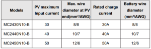
2.2 Wiring Specifications
Wiring and installation must comply with national and local electrical code requirements. PV and battery connection wires must be selected according to the rated current. Refer to the following table for wiring specifications:
2.3 Installation and Wiring
Warning
- Danger, Explosion! Never install the controller and a vented battery in the same enclosed space! Also, do not install in an enclosed place where battery gas may collect.
- Danger, High Voltage! Photovoltaic arrays may generate very high open-circuit voltages. Disconnect the circuit breaker or fuse before wiring, and be very careful during wiring.
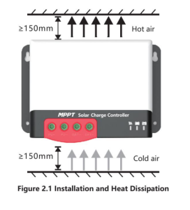
- When installing the controller, ensure that there is enough air to flow through its heat sink, leaving at least 150mm above and below the controller to ensure natural convection for heat dissipation. If the controller is installed in a closed box, ensure reliable heat dissipation through the box.
Step 1: Choose an installation location
Avoid installing the controller in a place free of direct sunlight, high temperatures, and water, and ensure good ventilation around the controller.
Step 2: Mark the mounting position according to the mounting dimensions of the controller.
At the 4 marks, drill 4 mounting holes of the appropriate size. Fix screws into the upper two mounting holes.
Step 3: Fasten the Controller
Align the controller’s fixing holes with the two pre-fixed screws, hang the controller up, and then fix the lower two screws.
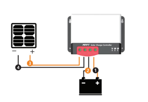
Step 4: Wire
For installation safety, we recommend the following wiring sequence; however, wiring in other sequences instead of this one will not damage the controller.
Warning
Danger—Electric shock hazards! We strongly recommend connecting a fuse or circuit breaker to the PV array and battery terminal to prevent electric shock hazards during wiring or error operation. Make sure that the fuse or circuit breaker is disconnected before wiring.
High-voltage hazards! Photovoltaic arrays may generate very high open-circuit voltages. Disconnect the circuit breaker or fuse before wiring, and be very careful during wiring.
Danger, Explosion hazards! If the positive and negative terminals of the battery and the wires connected to them are short-circuited, it may cause a fire or explosion. Please be very careful in operation. Please connect the battery first, and then the solar panel. Please follow the “ +” first and “-” next method when wiring.
When all wires are connected firmly and reliably, check whether the wiring is proper and whether the polarity is reversed. After confirmation, connect the battery fuse or circuit breaker and observe whether the LED indicator is on. If not, disconnect the fuse or circuit breaker immediately and check whether the wiring is correct.
As the battery is energized correctly, connect the solar panel. If there is sufficient sunlight, the controller’s charge indicator will be steady on or flash and start charging the battery.
When the controller has stopped charging for 10 minutes, the battery’s reverse polarity can damage its internal components.
Note:
- Note that the battery fuse shall be installed as close as possible to the battery terminal. The recommended distance is not more than 150 mm.
- The battery temperature is 25°C (fixed value) when the controller is not connected to a remote temperature sensor.
3. PRODUCT OPERATION AND DISPLAY
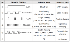
3.1 LED Indicators
There are a total of three indicators on the controller.
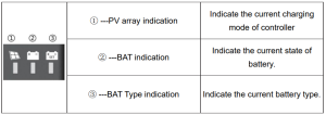
PV array indicator
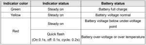
BAT indicator
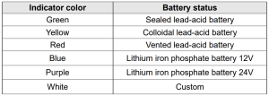
BAT Type Indication
3.2 Key Operation
There is a key on the controller that is used in conjunction with the battery type indicator to select the battery type. The specific operation mode is as follows:
Press and hold the key for 8 seconds in the current operating state. The battery type indicator (the color displayed is that of the previously saved battery type) starts to flash (the controller turns off charging and other works and enters an idle state).
At this point, each time the key is pressed, the battery type indicator changes color to correspond to the battery type. After selecting the battery type, press and hold the key for 8 seconds or maintain no operation for 15 seconds.
Then, the controller will automatically save the currently set battery type and enter the normal operating mode.
In addition, if you press and hold the key for 20 seconds, the controller will restore the factory default parameters.
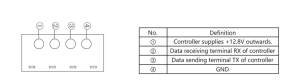
3.3 TTL Communication
Users can utilize external communication equipment (such as Bluetooth BT-2) or a communication protocol to perform data monitoring, parameter setting, and other operations for the controller via the port. The interface is defined as follows:
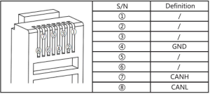
3.4 CAN communication
An optional built-in CAN communication function and RV-C protocol.
4. PRODUCT PROTECTION AND SYSTEM MAINTENANCE
4.1 Protections
- Waterproofing protection
Rating: IP32
- Input power limited protection
When the solar panel’s power is higher than the rated value, the controller will limit the power within the rated power range to prevent damage by overcurrent, and the controller will enter the limiting charge.
- Battery reverse polarity protection
If the battery polarity is reversed, the system will not work, but will not burn out the controller.
- PV input end voltage is too high
If the voltage at the PV array input end is too high, the controller will automatically shut off the PV input.
- PV input end short circuit protection
If the voltage at the PV array input end is short-circuited, the controller will turn off charging; after the short circuit is removed, charging will automatically recover.
- PV input reverse polarity protection
When the polarity of the PV array is reversed, the controller is not damaged, and normal operation will continue after the wiring error is corrected.
- Night reverse charging protection
Prevent battery discharge through the solar panel at night.
- TVS lightning protection
- Over-temperature protection
When the controller’s temperature exceeds the set value, it will reduce or stop the charging power.
4.2 System Maintenance
- Inspections are recommended twice yearly to maintain the controller’s best long-term performance.
- Ensure the airflow around the controller is not obstructed, and remove any dirt or debris from the heat sink.
- Check if the insulation layers of all exposed wires are damaged due to sun exposure, friction with other objects nearby, dry rot, destruction by insects or rodents, etc. If so, it is necessary to repair or replace the wire.
- Verify if the indicators are consistent with the device’s operations. If necessary, corrective actions should be taken for any malfunctions or error indications.
- Check all wiring terminals for corrosion, insulation damage, signs of high temperature, or burning/discoloration.
Tighten terminal screws.
- Check for dirt, insects nesting, and corrosion, and clean as required.
- If the lightning arrester has failed, replace it in time to protect the user’s controller and other devices from damage by lightning operations.
- Please note to take corrective actions for any malfunctions or error indications if necessary.
Warning: Danger, electric shock hazards! Ensure all power supplies to the controller have been disconnected before checking or operating as above.
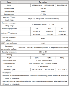
5. TECHNICAL PARAMETERS
5.1 Electrical parameters
5.2. Battery type default parameters
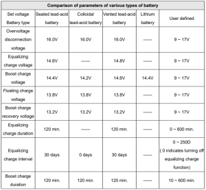
If a user-defined battery is used, the default voltage parameters of the system are the same as those of the sealed lead-acid battery. The following logic must be followed when you modify battery charge and discharge parameters:
Overvoltage disconnection voltage> charge limit voltage ≥ equalizing charge voltage ≥ boost charge voltage ≥ floating charge voltage> boost charge recovery voltage;
Overvoltage disconnection voltage> Overvoltage disconnection recovery voltage;
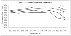
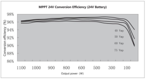
6. CONVERSION EFFICIENCY CURVE
6.1 12V System
6.2 24V System
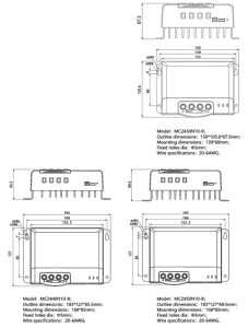
 7. PRODUCT DIMENSIONS
Made In China.
Recommended For Your Project
VEVOR 40A MPPT Solar Charge Controller, 12V / 24V Auto DC Input Manual


Reviews
There are no reviews yet.