Discover the ultimate guide to maximizing the performance and longevity of your VEVOR 20A MPPT Solar Charge Controller with our comprehensive product manual. Designed for both novice and experienced users, this manual offers step-by-step instructions for setting up, troubleshooting, and optimising your 12V / 24V Auto DC Input Solar Panel Regulator Charger.
With detailed sections covering everything from initial installation to advanced configurations, you’ll find valuable insights to ensure efficient charging of Sealed (AGM), Gel, Flooded, and Lithium batteries. The user-friendly format, complemented by clear diagrams and an intuitive layout, makes it easy to follow and apply.
Additionally, including the LCD and temperature sensor cable functionalities is thoroughly explained, helping you achieve optimal performance under various conditions. Download your VEVOR 20A MPPT Solar Charge Controller manual today and unlock the full potential of your solar energy system.
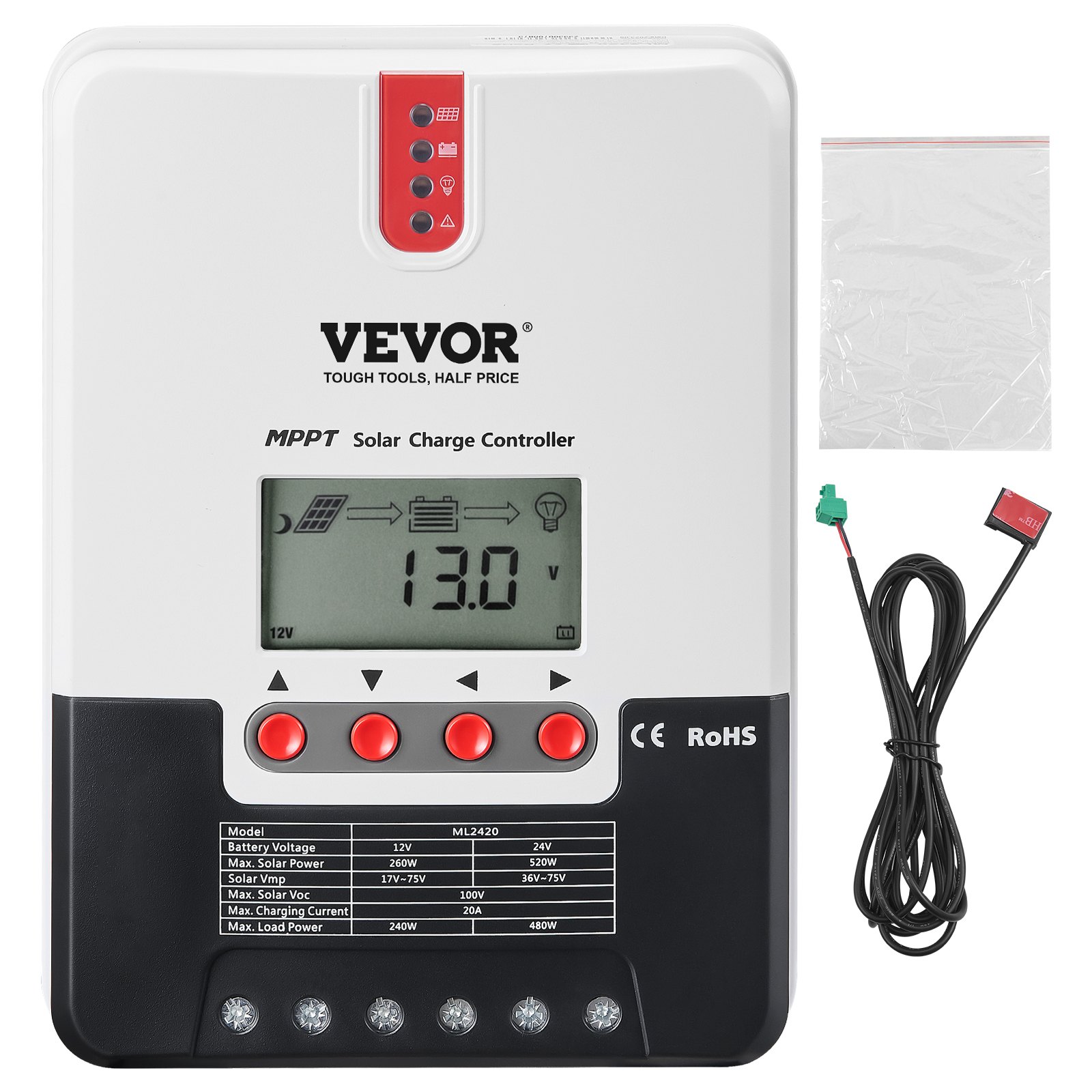
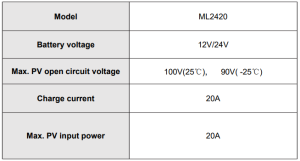
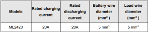
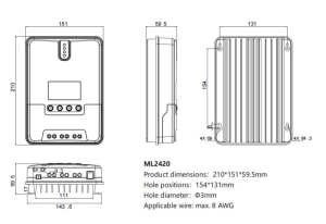
Model: ML2420
SAFETY INSTRUCTIONS
- As this controller deals with voltages that exceed the top limit for human safety, do not operate it before reading this manual carefully and completing safety operation training.
- The controller has no internal components that need maintenance or service; thus do not attempt to disassemble or repair the controller.
- Install the controller indoors, and avoid component exposure and water intrusion.
- During operation, the radiator may reach a very high temperature; therefore, install the controller in a place with good ventilation conditions.
- It’s recommended that a fuse or breaker be installed outside the controller.
- Before installing and wiring the controller, disconnect the photovoltaic array and the fuse or breaker close to the battery terminals.
- After installation, check if all connections are solid and reliable to avoid loose connections that may lead to dangers caused by heat accumulation.
1. PRODUCT INTRODUCTION
1.1 Product Overview
- This product can monitor the solar panel’s generating power and track the highest voltage and current values (VI) in real time, enabling the system to charge the battery at maximum power. It’s designed to be used in off-grid solar photovoltaic systems to coordinate the operation of the solar panel, battery, and load, functioning as the core control unit in these systems.
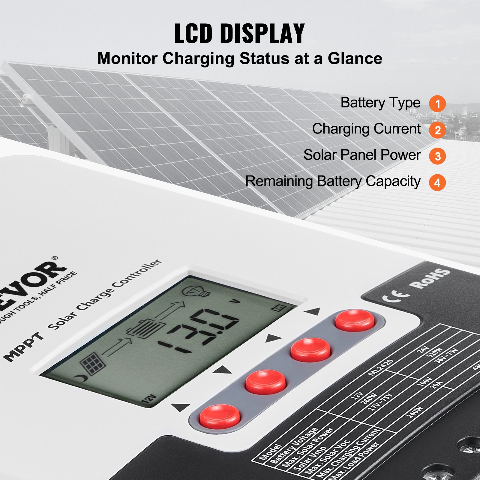
- This product features an LCD screen that can dynamically display the operating status, operating parameters, controller logs, control parameters, etc. Users can conveniently check parameters by key and modify control parameters to cater to system requirements.
- The controller utilizes the standard Modbus communication protocol, making it easy for users to check and modify system parameters on their own. Besides, by providing free monitoring software, we give users the maximum convenience to satisfy their varied needs for remote monitoring.
- Comprehensive electronic fault self-detecting functions and powerful electronic protection functions built inside the controller can prevent component damage caused by installation errors or system failures to the greatest extent possible.
1.2 Product Features
- With the advanced dual-peak or multi-peak tracking technology, when the solar panel is shadowed or part of the panel fails, resulting in multiple peaks on the I-V curve, the controller can still accurately track the maximum power point.
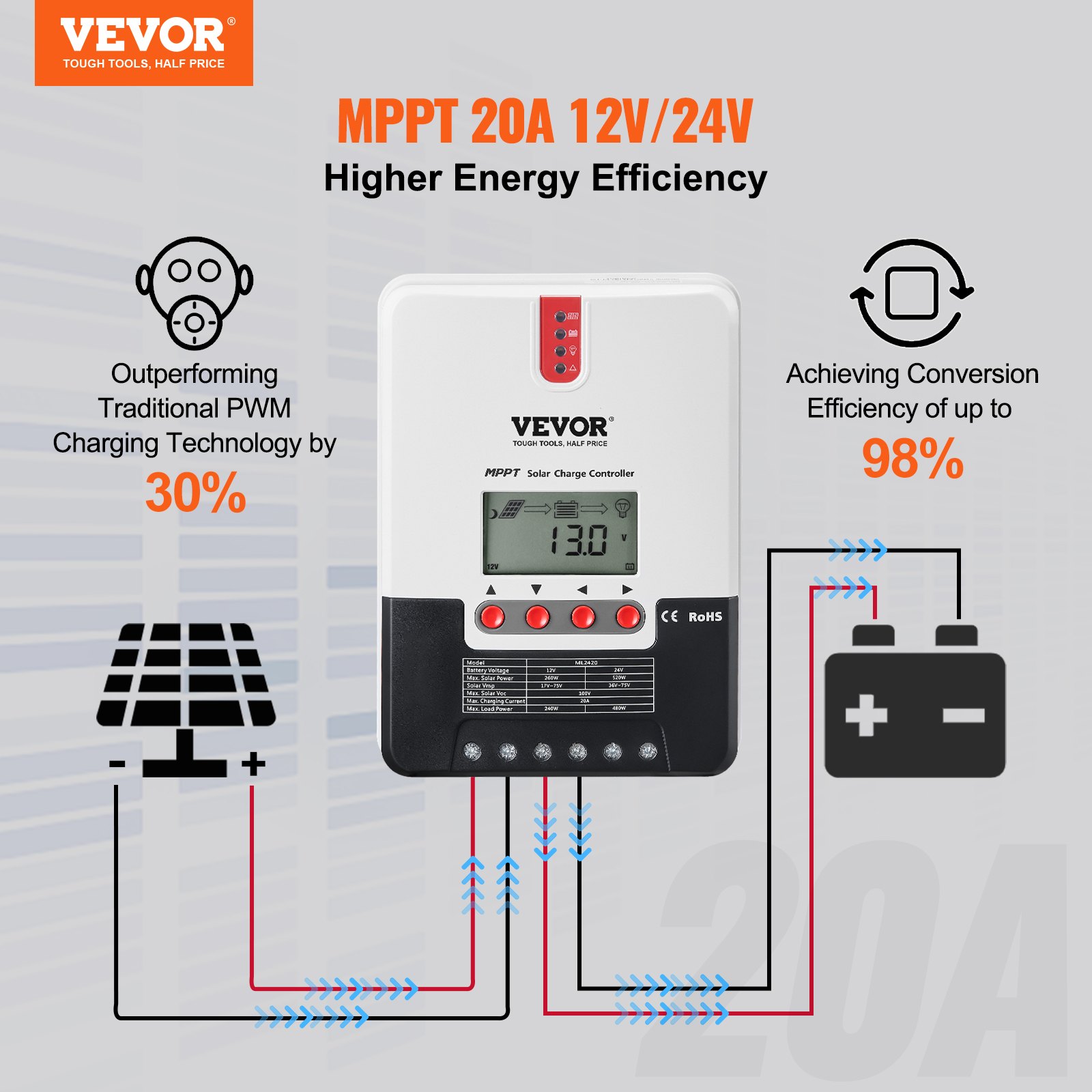
- A built-in maximum Powerpoint tracking algorithm can significantly improve the energy utilization efficiency of photovoltaic systems and raise the charging efficiency by 15% to 20% compared with the conventional PWM method.
- A combination of multiple tracking algorithms enables accurate tracking of the optimum working point on the I-V curve in an extremely short time.
- The product boasts an optimum MPPT tracking efficiency of up to 99.9%.
- Advanced digital power supply technologies raise the circuit’s energy conversion efficiency to as high as 98%.
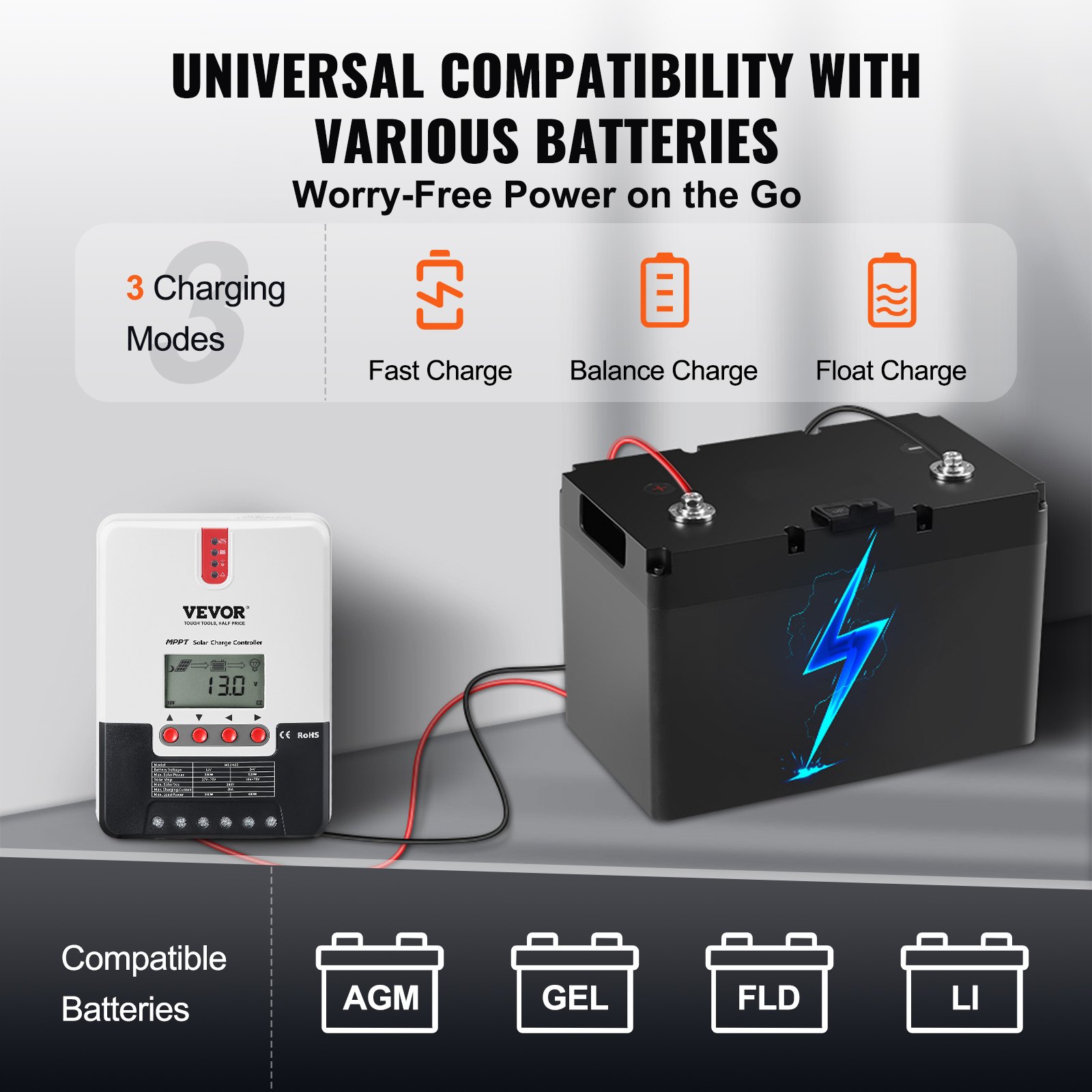
- Charging program options are available for different types of batteries, including gel batteries, sealed batteries, open batteries, and lithium batteries.
- The controller features a limited current charging mode. When the solar panel power exceeds a certain level and the charging current is larger than the rated current, the controller will automatically lower the charging power and bring the charging current to the rated level.
- Instantaneous large current startup of capacitive loads is supported.
- Automatic recognition of battery voltage is supported.
- LED fault indicators and an LCD screen that can display abnormality information help users quickly identify system faults.
- The historical data storage function is available, and data can be stored for up to a year.
- The controller has an LCD screen with which users can check device operating data and statuses and modify controller parameters.
- The controller supports standard Modbus protocol, fulfilling the communication needs of various occasions.
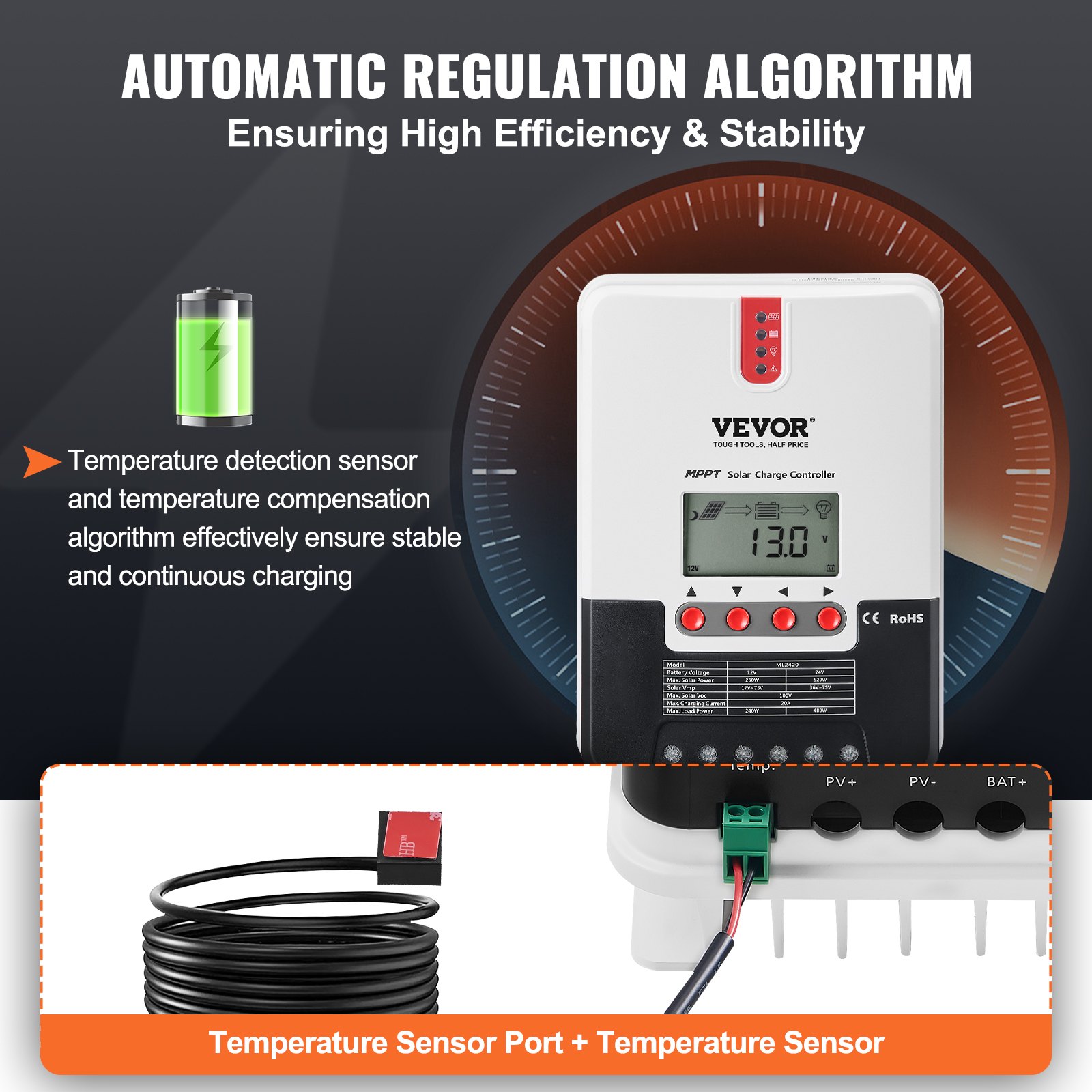
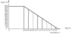
- The controller employs a built-in over-temperature protection mechanism. When the temperature surpasses the set value, the charging current will decline in linear proportion to the temperature to curb the controller’s temperature rise, effectively keeping it from being damaged by overheating.
- Featuring a temperature compensation function, the controller can automatically adjust charging and discharging parameters to extend the battery’s service life.
- TVS lighting protection.
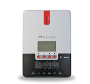
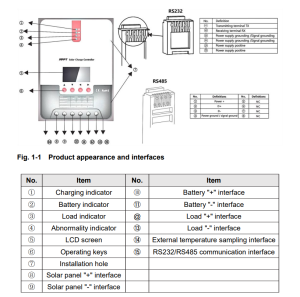
1.3 Exterior and Interfaces
1.4 Introduction to Maximum Power Point Tracking Technology
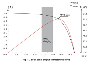
Maximum Power Point Tracking (MPPT) is an advanced charging technology that enables the solar panel to output more power by adjusting the electric module’s operating status. Due to the nonlinearity of solar arrays, a maximum energy output point (maximum power point) exists on their curves.
Unable to continuously lock onto this point to target the battery, conventional controllers (employing switching and PWM charging technologies) can’t get most of the power from the solar panel. Buta solar charge controller featuring MPPT technology can continuously track the array’s maximum power point to get the maximum amount of power to charge the battery.
Take a 12V system as an example. As the solar panel’s peak voltage (Vpp)is approximately 17V while the battery’s voltage is around 12V, when charging with a conventional charge controller, the solar panel’s voltage will stay at around 12V, failing to deliver the maximum power.
However, the MPPT controller can overcome the problem by adjusting the solar panel’s input voltage and current in real time, realizing a maximum input power.
Compared with conventional PWM controllers, the MPPT controller can maximize the solar panel’s maximum power and provide a larger charging current. Generally speaking, the latter can raise the energy utilisation ratio by 15% to 20%.
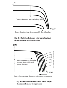
Meanwhile, due to changing ambient temperature and illumination conditions, the max. Power point varies frequently, and our MPPT controller can adjust parameter settings according to the environmental conditions in real time, to always keep the system close to the max. operating point.
The whole process is entirely automatic without the need for human intervention.
1.5 Charging Stage Introductions
As one of the charging stages, MPPT cannot be used alone. It is usually required to combine boost charge, floating charge, equalising charge, and other charging methods to complete the battery charging process.
A complete charging process includes Quick, holding, and floating charges. The charging curve is shown below:
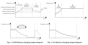
- Fast charging
At the fast charging stage, as the battery voltage has not reached the set value of full voltage (i.e. equalizing/ boost voltage) yet, the controller will perform MPPT charging on the battery with the maximum solar power. When the battery voltage reaches the preset value, constant voltage charging will begin.
- Sustaining charging
When the battery voltage reaches the set value of holding voltage, the controller will perform constant voltage charging. This process will no longer include MPPT charging, and the charging current will gradually decrease with time. Holding charge comes in two stages, i.e. equalizing charge and boost charge. The two stages are conducted without repetition, in which equalizing charge is started once every 30 days.
- Boost charging
By default, boost charging generally lasts for 2h, but users can adjust preset duration values and boost voltage point according to their actual needs. When the duration reaches the set value, the system will then switch to floating charging.
- Equalizing charging
Warning: Risk of explosion!
In equalizing charging, an open lead-acid battery can produce explosive gas, therefore, the battery chamber shall have good ventilation conditions.
Note: risk of equipment damage!
Equalizing charging may raise the battery voltage to a level that may cause damage to sensitive DC loads. Check and ensure that allowable input voltages of all the loads in the system are greater than the set value for battery equalizing charging.
Note: risk of equipment damage!
Overcharging or too much gas generated may damage battery plates and cause active material on the battery plates to scale off. Equalising charging to an excessively high level or for too long a period may cause damage.
Read carefully the actual requirements of the battery deployed in the system. Some types of batteries benefit from regular equalizing charging, which can stir the electrolyte, balance the battery voltage and finish the electrochemical reaction. Equalizing charging raises the battery voltage to a higher level than the standard supply voltage and gasifies the electrolyte.
If the controller then automatically steers the battery into equalising charging, the charging duration is 120 minutes (default). To avoid too much gas generated or battery overheating, equalising charging and boosting charging won’t repeat in one complete charging cycle.
Note:
- When the system can’t continuously stabilize the battery voltage to a constant level due to the installation environment or working loads, the controller initiates a timing process. Three hours after the battery voltage reaches the set value, the system automatically switches to equalising charging.
- If the controller clock is not calibrated, it will equalize charging regularly according to its internal clock.
- Floating charging
When the sustaining charging stage is finished, the controller switches to floating charging, in which the controller lowers the battery voltage by diminishing the charging current and keeps the battery voltage at the set floating charging voltage.
In the floating charging process, very light charging is carried out to maintain the battery’s full state. At this stage, the loads can access almost all the solar power. If the loads consume more power than the solar panel can provide, the controller cannot keep the battery voltage at the floating charging stage.
When the battery voltage drops to the set value to return to boost charging, the system will exit floating charging and re-enter fast charging.
2. PRODUCT INSTALLATION
2.1 Installation Precautions
- Be very careful when installing the battery. For open lead-acid batteries, wear a pair of goggles during installation, and in case of contact with battery acid, flush with water immediately.
- To prevent the battery from being short-circuited, no metal objects shall be placed near the battery.
- Acid gas may be generated during battery charging; thus make sure the ambient environment is well ventilated.
- Keep the battery away from fire sparks, as the battery may produce flammable gas.
- When installing the battery outdoors, take sufficient measures to keep the battery from direct sunlight and rainwater intrusion.
- Loose connections or corroded wires may generate excessive heat, which may further melt the wire’s insulation layer, burn surrounding materials, or even cause a fire. Therefore, make sure all connections are tightened securely. Wires should be appropriately fixed with ties, and when needs arise to move things, avoid wires swaying to keep connections from loosening.
- When connecting the system, the output terminal’s voltage may exceed the top limit for human safety. If the operation needs to be done, use insulation tools and keep your hands dry.
- The wiring terminals on the controller can be connected to a single battery or a pack of batteries. The following descriptions in this manual apply to systems employing either a single battery or a pack of batteries.
- Follow the safety advice given by the battery manufacturer.
- When selecting connection wires for the system, follow the criterion that the current density is not larger than 4A/mm2
- Connect the controller’s earth terminal to the ground.
2.2 Wiring Specifications
Wiring and installation methods must comply with national and local electrical specifications. The wiring specifications of the battery and loads must be selected according to rated currents, and see the following table for wiring specifications:
Warning
- Risk of explosion! Never install the controller and an open battery in the same enclosed space! Nor shall the controller be installed in an enclosed space where battery gas may accumulate.
- Danger of high voltage! Photovoltaic arrays may produce a very high open-circuit voltage. Open the breaker or fuse before wiring, and be very careful during the wiring process.
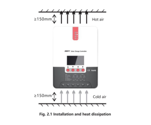
- When installing the controller, ensure enough air flows through its radiator and leave at least 150mm of space above and below it to ensure natural convection for heat dissipation.
If the controller is installed in an enclosed box, ensure the box delivers a reliable heat dissipation effect.
Step 1: Choose the installation site
Do not install the controller in a place subject to direct sunlight, high temperature, or water intrusion, and ensure the ambient environment is well ventilated.
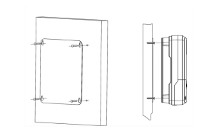
Step 2: First, place the installation guide plate in a proper position, use a marking pen to mark the mounting points, drill four mounting holes at the marked points, and fit screws in.
Step 3: Fix the controller
Aim the controller’s fixing holes at the screws fit in Step 2 and mount the controller on.
Step 4: Wire
First, remove the two screws on the controller and then begin wiring operation. To guarantee installation safety, we recommend the following wiring order; however, you can choose not to follow this order, and the controller will not be damaged.
Warning
- There is a risk of electric shock! We strongly recommend that fuses or breakers be connected at the photovoltaic array side, load side, and battery side to avoid electric shock during wiring operation or faulty operations, and that the fuses and breakers be in an open state before wiring.
- Danger of high voltage! Photovoltaic arrays may produce a very high open-circuit voltage. Open the breaker or fuse before wiring, and be very careful during the wiring process.
- There is a risk of explosion! Once the battery’s positive and negative terminals or leads that connect to the two terminals get short-circuited, a fire or explosion will occur. Always be careful when operating.
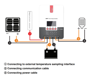
First, connect the battery, then the load, and finally, the solar panel. When wiring, follow the order of “+” and then “-.”
4. Power on
After connecting all power wires solidly and reliably, check whether wiring is correct and if the positive and negative poles are reversely connected. After confirming that no faults exist, first close the fuse or breaker of the battery, then see whether the LED indicators light up and the LCD screen displays information. If the LCD screen fails to display information, open the fuse or breaker immediately and recheck if all the connections are correctly done.
If the battery functions normally, connect the solar panel. If sunlight is intense enough, the controller’s charging indicator will light up or flash and begin to charge the battery. After successfully connecting the battery and photovoltaic array, finally close the load’s fuse or breaker, and then you can manually test whether the load can be turned on and off normally. For details, refer to the information about load working modes and operations.
Warning
- When the controller is in a normal charging state, disconnecting the battery will negatively affect the DC loads, and in extreme cases, the loads may get damaged.
- If the battery’s poles are reversely connected within 10 minutes after the controller stops charging, the controller’s internal components may become damaged.
Note
- The battery’s fuse or breaker shall be installed as close to the battery side as possible, and it’s recommended that the installation distance be no more than 150mm.
- If no remote temperature sensor is connected to the controller, the battery temperature value will stay at 25 °C.
- If an inverter is deployed in the system, directly connect the inverter to the battery and do not connect it to the controller’s load terminals.
3. Solar Charge Controller Operation and Display
3.1 LED Indicators
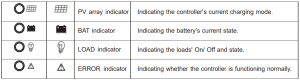
PV array indicator
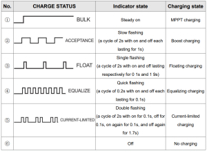
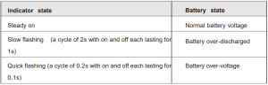
BAT indicator
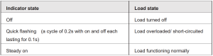
LOAD indicator
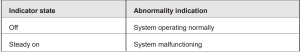
ERROR indicator
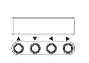
3.2 Keys Operation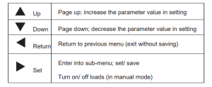
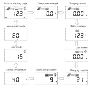
3.3 LCD Startup and Main Interface
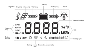
Startup Interface
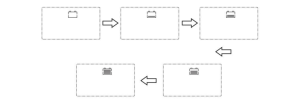
During startup, the 4 indicators will first flash successively. After self-inspection, the LCD screen starts and displays the battery’s voltage level, which will be either a fixed voltage selected by the user or an automatically recognized voltage.
Main Interface
3.4 Load Mode Setting Interface
3.4.1 Load modes introduction
This controller has 5 load operating modes, which will be described below:
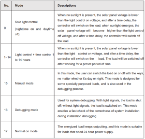
3.4.2 Load mode adjustment
Users can adjust the load mode as needed; the default mode is debugging mode (see “load modes introduction”). The method for adjusting load modes is as follows:
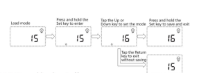
3.4.3 Manual Load on/off Page
Manual operation is effective only when the load mode is manual (15). Tap the Set key to switch on/off the load under any main interference.
3.5 System Parameter Settings
Under any interface other than load modes, press and hold the Set key to enter into the parameter setting interface.
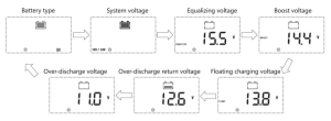
After entering the setting interface, tap the Set key to switch to the setting, and tap the Up or Down key to increase or decrease the parameter value in the menu.
Then tap the Return key to exit (without saving parameter settings), or press and hold the Set key to save the setting and exit.
Note: After setting the system voltage, the power supply has to be switched off and then on again; otherwise, the system may work with an abnormal system voltage.
The controller enables users to customize the parameters according to the actual conditions. Still, parameter settings must be made under the guidance of a professional; otherwise, faulty parameter settings may render the system unable to function normally.
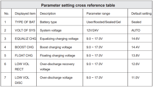
For details about parameter settings, see table 3
4. PRODUCT PROTECTION AND SYSTEM MAINTENANCE
4.1 Protections
- Waterproofing protection
Rating: IP32
- Input power limited protection
When the solar panel’s power is higher than its rated value, the controller will limit the panel’s power within the rated power range to prevent damage by overcurrent, and the controller will enter the limiting charge.
- Battery reverse polarity protection.
If the battery polarity is reversed, the system will not work but will not burn out the controller.
- The PV input end voltage is too high
If the voltage at the PV array input end is too high, the controller will automatically shut off the PV input.
- PV input end short circuit protection
If the voltage at the PV array input end is short-circuited, the controller will turn off charging; after the short circuit is removed, charging will automatically recover.
- PV input reverse polarity protection
When the polarity of the PV array is reversed, the controller will not be damaged, and normal operation will continue after the wiring error is corrected.
- Night reverse charging protection.
Prevent battery discharge through the solar panel at night.
- TVS lightning protection
- Over-temperature protection
When the controller temperature exceeds the set value, charging power will decrease or halt.
See the following diagram:
4.2 System Maintenance
- Inspections are recommended twice yearly to maintain the controller’s long-term performance.
- Ensure the airflow around the controller is not obstructed, and remove any dirt or debris from the heat sink.
- Check if the insulation layers of all exposed wires are damaged due to sun exposure, friction with other objects nearby, dry rot, destruction by insects or rodents, etc. If so, it is necessary to repair or replace the wire.
- Verify if indicators are consistent with device operations. Please note that corrective actions are necessary for any malfunctions or error indications.
- Check all wiring terminals for corrosion, insulation damage, signs of high temperature, or burning/discoloration, and tighten the terminal screws firmly.
- Check for dirt, insects nesting, and corrosion, and clean as required.
- If the lightning arrester has failed, replace it in time to protect the user’s controller and other devices from damage by lightning operations. Please note to take corrective actions for any malfunctions or error indications if necessary.
Warning: There is a risk of electric shock! Before carrying out the above checks or operations, always make sure all power supplies of the controller have been cut off!
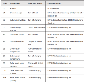
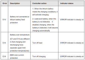
4.3 Abnormality Display and Warnings
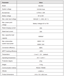
5. Solar Charge Controller Technical Parameters
5.1 Electrical parameters
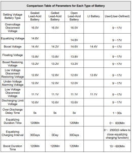
5.2. Battery type default parameters
When selecting User, the battery type is to be self-customized. In this case, the default system voltage parameters are consistent with those of the sealed lead-acid battery.
When modifying battery charging and discharging parameters, the following rule must be followed:
- Over-voltage cut-off voltage> Charging limit voltage≥ Equalizing voltage≥ Boost voltage ≥ Floating charging voltage >Boost return voltage;
- Over-voltage cut-off voltage > Over-voltage cut-off return voltage;
- Low-voltage cut-off return voltage >Low-voltage cut-off voltage≥Discharging limit voltage;
- Under-voltage warning return voltage > Under-voltage warning voltage≥ Discharging limit voltage;
- Boost return voltage > Low-voltage cut-off return voltage
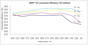
6. CONVERSION EFFICIENCY CURVE
6.1 12V System Conversion
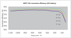
6.1 24V System Conversion
7. Solar Charge Controller Product Dimensions
Recommended For Your Project
VEVOR 20A MPPT Solar Charge Controller, 12V / 24V Auto DC Input Manual
Reviews
There are no reviews yet.