
Unlock the full potential of your VEVOR 3 in 1 Plasma Cutter Welder Machine with our comprehensive product manual download. This detailed guide covers everything you need to know about the CT-520 TIG/MMA Plasma Cutter Combo Machine, offering step-by-step instructions for setup, optimization, and troubleshooting.
Whether you’re using the Non-Touch Pilot Arc Plasma Cutter, the TIG Welder, or the Stick Welder, our manual ensures you make the most of your Digital 110/220V Dual Voltage IGBT Inverter. Perfect for both beginners and seasoned professionals, this manual is designed to simplify your work, enhance efficiency, and ensure safety.
Download it now to get started confidently and efficiently with your VEVOR machine.
VEVOR PLASMA CUTTER WELDER MACHINE MANUAL
MACHINE OPERATING SAFETY
- Do not switch the function modes while the Plasma Cutter Welder Machine is operating. Switching the function modes during welding can damage the machine, and the damage will not be covered under warranty.
- Disconnect the electrode-holder cable from the machine before switching it on to avoid arcing if the electrode is in contact with the work piece.
- Operators should be trained and or qualified.
Electric shock: It can kill
- Touching live electrical parts can cause fatal shocks or severe burns. The electrode and work circuit are electrically live whenever the output is on. The input power circuit and internal machine circuits are also live when power is on. In MIG/MAG welding, the wire, drive rollers, wire feed housing, and all metal parts touching the welding wire are electrically live. Incorrectly installed or improperly grounded equipment is dangerous.
- Connect the primary input cable according to American standards and regulations.
- Avoid all contact with live electrical parts of the welding/cutting circuit, electrodes, and wires with bare hands.
- The operator must wear dry welding gloves while he/she performs the welding/cutting task.
The operator should keep the workpiece insulated from himself/herself. - Keep cords dry, free of oil and grease, and protected from hot metal and sparks.
- Frequently inspect the input power cable for wear and tear. If damaged, replace the cable immediately. Bare wiring is dangerous and can kill.
- Do not use damaged, undersized, or badly joined cables.
- Do not abuse cables. Do not bend cables.
- We recommend using the (RCD) safety switch with this equipment to detect any current leakage to earth.
Fumes and gases are dangerous.
- Smoke and gas generated whilst welding or cutting can be harmful to people’s health. Welding produces fumes and gases. Breathing these fumes and gases can be hazardous to your health. Do not breathe the smoke and gas generated whilst welding or cutting, keep your head out of the fumes.
- Keep the working area well ventilated, use fume extraction or ventilation to remove welding/cutting fumes and gases.
- In confined or heavy fume environments, always wear an approved air-supplied respirator.
- Welding/cutting fumes and gases can displace air and lower the oxygen level, causing injury or death. Be sure the breathing air is safe.
Do not weld or cut in locations near degreasing, cleaning, or spraying operations. The arc’s heat and rays can react with vapours to form highly toxic and irritating gases. - Materials such as galvanized, lead, or cadmium-plated steel contain elements that can give off toxic fumes when welded or cut. Do not weld or cut these materials unless the area is very well ventilated and/or you are wearing an air-supplied respirator.
Arc rays
- Harmful to people’s eyes and skin. Arc rays from the welding/cutting process produce intense visible and invisible ultraviolet and infrared rays that can burn eyes and skin. Always wear a welding helmet with the correct shade of filter lens and suitable protective clothing, including welding gloves, whilst the welding/cutting operation is performed.
- Measures should be taken to protect people in or near the surrounding working area. Protective screens or barriers should be used to protect others from flash, glare, and sparks, and warnings should be given to those who do not watch the arc.
Fire hazard.
- Welding or cutting on closed containers, such as tanks, drums, or pipes, can cause them to explode. Flying sparks from the welding/cutting arc, hot workpiece, and hot equipment can cause fires and burns. Accidental contact of the electrode with metal objects can cause sparks, explosions, overheating, or fire. Check and be sure the area is safe before doing any welding/cutting.
- The welding/cutting sparks and spatter may cause fire; therefore, remove any flammable materials well away from the working area. If flammable materials and containers cannot be moved from the welding/cutting area, cover them with approved covers.
- Do not weld/cut on closed containers such as tanks, drums, or pipes, unless they are correctly prepared according to the required Safety Standards to ensure that flammable or toxic vapours and substances are totally removed, as these can cause an explosion even though the vessel has been “cleaned”. Vent hollow castings or containers before heating, cutting, or welding. They may explode.
- Do not weld/cut where the atmosphere may contain flammable dust, gas, or liquid vapours (such as petrol).
- Have a fire extinguisher nearby and know how to use it. Be alert that welding/cutting sparks and hot materials from welding/cutting can easily go through small cracks and openings to adjacent areas. Be aware that welding/cutting on a ceiling, floor, bulkhead, or partition can cause fire on the hidden side.
Gas Cylinders.
- Shielding gas cylinders contain gas under high pressure. If damaged, a cylinder can explode. Because gas cylinders are normally part of the welding/cutting process, be sure to treat them carefully. CYLINDERS can explode if damaged.
- Protect cylinders from excessive heat, mechanical shock, physical damage, slag, open flames, sparks, and arcs.
- Ensure cylinders are held securely and upright to prevent tipping or falling over.
- Never allow the welding/cutting electrode or earth clamp to touch the gas cylinder; do not drape welding cables over the cylinder.
- Never weld/cut on a pressurised gas cylinder, it will explode and kill you.
- Open the cylinder valve slowly and turn your face away from the cylinder outlet valve and gas regulator.
Gas buildup.
- The buildup of gas can create a toxic environment and deplete the oxygen content in the air, resulting in death or injury. Many gases used in welding and cutting are invisible and odourless.
Shut off the shielding gas supply when not in use. - Always ventilate confined spaces or use an approved air-supplied respirator.
Electronic magnetic fields.
- MAGNETIC FIELDS can affect Implanted Medical Devices.
- Wearers of Pacemakers and other Implanted Medical Devices should keep away.
- Implanted Medical Device wearers should consult their doctor and the device manufacturer before going near any electric welding, cutting or heating operation.
Noise can damage hearing.
- Noise from some processes or equipment can damage hearing.
- Wear approved ear protection if the noise level is high.
Hot parts
- Items being welded/cut generate and hold high heat and can cause severe burns.
- Do not touch hot parts with your bare hands. Allow a cooling period before working on the welding/cutting gun. Use insulated welding gloves and clothing to handle hot parts and prevent burns.
CAUTION
Working Environment.
- The environment in which this welding/cutting equipment is installed must be free of grinding dust, corrosive chemicals, flammable gas or materials, etc, and at no more than a maximum of 80% humidity.
- When using the machine outdoors, protect it from direct sunlight, rain, snow, etc. The working environment should be maintained between -10°C and +40°C.
- Keep this equipment 30cm distant from the wall.
- Ensure the working environment is well ventilated.
Safety Tips.
- Ventilation
This equipment is small-sized, compact in structure, and of excellent performance in amperage output. The fan is used to dissipate heat generated by this equipment during the welding/cutting operation. Important: Maintain good ventilation of the louvres of this equipment. The minimum distance between this equipment and any other objects in or near the working area should be 30 cm. Good ventilation is of critical importance for the normal performance and service life of this equipment.
- Thermal Overload protection
Should the machine be used to an excessive level, in a high-temperature environment, a poorly ventilated area, or if the fan malfunctions, the Thermal Overload Switch will be activated, and the machine will cease to operate. Under these circumstances, leave the machine switched on to keep the built-in fan working to bring down the temperature inside the equipment. The machine will be ready for use again when the internal temperature reaches a safe level.
- Over-Voltage Supply
Regarding the power supply voltage range of the machine, please refer to the “Main parameter” table. This equipment is of automatic voltage compensation, which enables the maintenance of the voltage range within the given range.
If the input power supply’s voltage exceeds the stipulated value, damage to the equipment’s components can occur. Please ensure your primary power supply is correct.
Do not touch the output terminals while the machine is in operation. An electric shock may occur.
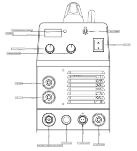
LOCAL DESCRIPTION
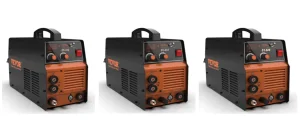
CT-312 CT-520 is a multifunctional welding and cutting machine developed using internationally advanced inverter technology. It has three functions: argon arc welding, manual arc welding, and plasma cutting.
The emergence of inverter arc welding equipment is attributed to the emergence of inverter power theory and devices. The inverter arc welding/cutting power supply uses high-power device IGBT tubes to convert 50/60Hz power frequency into high frequency (such as 50KHz or above), then reduces voltage and rectifies it, and outputs a high-power DC source through pulse width modulation technology (PWM). The weight and volume of the main transformer are significantly reduced, and the efficiency is increased by more than 30%. Experts hail the emergence of inverter welding machines as a revolution in the welding machine industry.
Our welding power supply can provide stronger, more concentrated, and more stable arcs. When conducting short circuit droplet transfer, the reaction between the welding rod and the workpiece becomes faster after a short circuit occurs. This means that welding machines with different dynamic characteristics can be efficiently designed, and even the characteristics can be adjusted to make the arc softer or harder.
When using argon arc welding, it is easy to start the arc, the arc is concentrated, and has the characteristics of early gas supply, delayed gas off, and stable arc. As a manual arc welding machine, the external factors of the welding machine are oblique, and the welding current and thrust current are uniformly adjusted by the same potentiometer, which has good arc starting and constant power output during welding, achieving the best results in both weld formation and internal quality.
In a plasma cutting process, the arc undergoes forced compression by rapidly flowing air, and the temperature rises to a height of 1000015000 ℃ in the Ionized state, forming a strong plasma arc. Using a plasma arc for rapid metal cutting concentrates heat and effectively obtains energy.
By utilizing it, an incredibly smooth cutting surface can be obtained, which brings convenience for subsequent processing.
CT-312 and CT-520 are widely used for welding and cutting carbon steel, stainless steel, alloy steel, copper, and other non-ferrous metals. They are compact, lightweight, efficient, energy-saving, stable, and reliable, with a conversion rate of over 85% for the entire machine.
Welcome users from all walks of life to use our products and provide valuable suggestions. We are committed to making our products and services perfect.
INSTALLATION INSTRUCTIONS
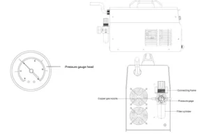
- Tighten the copper gas nozzle with sealing tape around the IN and OUT ends.
- Wrap the sealing tape around the meter head and tighten it in the installation position of the meter head.
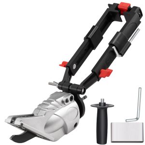
- Fix the connecting frame with nuts as shown in the figure at the installation Position of the pressure reducing valve behind the welding machine.
- Unscrew the rubber nut and fix the pressure-reducing valve on the connecting frame as shown in the figure.
- Turn on the air valve switch, lift the pressure regulating knob upwards, and adjust the air pressure (the scale in the gauge head is the value of Kg) to regulate the air pressure (increase the pressure by rotating towards “+” and decrease the pressure by rotating towards “-“), and then lower the pressure. Press the knob.
- The position of the meter head scale is shown in the figure. The indicated position is 4 kilograms of air pressure.
- When there is too much water in the filter cylinder, it should be opened. The water valve drains the water.
Plasma Cutter Welder Machine Installation Instructions
Our Plasma Cutter Welder Machine is equipped with a power supply voltage compensation device, which allows it to continue operating when the power supply voltage changes within ± 10% of the rated voltage.
When using longer cables, it is recommended to choose cables with a larger cross-section to reduce voltage drop. If the connecting cable is too long, it may significantly impact the welding machine’s arcing performance and even other system performance.
So we suggest that you use the recommended configuration length.
- Confirm that the welding machine vent is not covered or blocked to prevent cooling system failure.
- Connect the casing to a reliable grounding device using a conductor with a cross-sectional area of at least 6 square millimeters by connecting the grounding wire on the back of the welding machine to the grounding device, or confirm that the grounding terminal of the power socket has been reliably grounded separately. To ensure safety, both methods can also be used simultaneously.
- Using the manual arc welding (ARC) function
- Firstly, confirm that the cable is reliably connected to the welding pliers and quick plug, and then insert the quick plug into the quick socket with polarity “-” of the welding machine. Tighten firmly clockwise.
- Insert the quick plug of the circuit cable into the quick socket of the welding machine panel with polarity “+argon arc/manual”, and tighten it clockwise with force, while the ground wire clamp at the other end clamps the workpiece.
- Pay attention to the polarity of the wiring. Generally, there are two types of wiring methods for DC welding machines: direct connection and reverse connection.
Direct connection method: the welding handle is connected to the negative electrode, and the workpiece is connected to the positive electrode.
Reverse connection method: the workpiece is connected to the negative electrode, and the welding handle is connected to the positive electrode. - ‘When welding, it is selected according to the process requirements of the workpiece. If not appropriately chosen, an unstable arc will occur. Phenomena such as considerable splashing and sticking can be easily replaced with quick plugs to change polarity.
- Using the argon welding (TIG) function
- Connect the protective gas source properly. The gas supply channel should include gas cylinders, argon pressure-reducing flow meters, and gas pipes. The connection part of the gas pipe should be tightly tied with a clamp or other items to prevent leakage and air entry.
- Install the gas-electric integrated connector of the welding gun onto the interface of the welding machine panel and tighten it clockwise with a wrench. Insert the aviation plug on the welding gun into the corresponding interface of the Plasma Cutter Welder Machine panel and tighten the interface screws.
- Insert the quick plug of the circuit cable into the quick socket of the welding machine panel with polarity “+argon arc/manual”, and tighten it clockwise with force, while the ground wire clamp at the other end clamps the workpiece.
- Using the Cut function
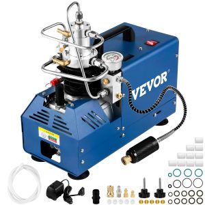
- Connect the gas inlet and compressed air source behind the cutting machine with a pressure-resistant gas pipe and tighten the interface with a clamp or other method. The air source should be dry and able to provide appropriate pressure and sufficient flow rate. Suppose your existing gas source cannot meet the above requirements. In that case, you should consider using a separate air compressor and gas pressure reducer with sufficient power to provide the required pressure and filter out impurities and moisture in the gas.
- Install the joint of the gas-electric integrated cutting gun onto the machine panel’s interface and tighten it clockwise with a wrench. Connect the cutting gun’s aviation plug to the corresponding interface of the machine panel and tighten the interface screws.
- Insert the circuit cable’s quick plug into the quick socket with polarity “+cutting” on the machine panel and tighten it clockwise with force, while the ground wire clamp at the other end clamps the workpiece.
- Given an encoder on the panel. The current regulation range of CT 416GD is 20-40.
- Connect the power code to the corresponding voltage level distribution box according to the welding machine’s input voltage level, and do not connect the wrong voltage. At the same time, ensure that the power supply voltage error is within the allowable range. After completing the above work, the welding machine will complete the installation work and can proceed with the operation.
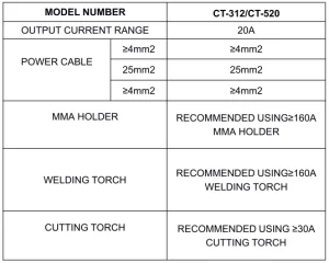
Related Device Specification Sheet
Plasma Cutter Welder Machine Operating Instructions
Use the argon welding function.
- Turn the power switch on the front panel to the “ON” position. The power indicator light will light up, and the internal fan will start rotating.
- Turn on the argon switch and adjust the gas flow rate to the rated standard.
- After pressing the switch on the welding torch, the solenoid valve will activate. You will hear the sound of high-frequency spark discharge inside the welding machine, and at the same time, argon gas will flow out of the welding torch nozzle. Note: When welding for the first time, you need to press and hold the switch for a few seconds before welding, until all the air in the air path is discharged, before starting welding. After you stop welding, there will still be argon gas flowing out for a few seconds. This is specially designed to ensure that the welding point is still protected before cooling. Therefore, when using it, it is necessary to maintain the welding position for a period of time after the arc is extinguished before removing the welding gun.
- Set appropriate welding current according to the thickness of the workpiece and process requirements.
- Maintain a distance of 1-4mm between the tungsten electrode and the welding workpiece, press the welding torch control switch, and high-frequency discharge will occur between the welding torch electrode and the workpiece. After ignition and arcing, the high-frequency arcing sparks inside the welding machine immediately disappear, and work can begin at this time.
Use the manual welding function.
- When you turn on the power switch, the power indicator light will be on, and the internal fan will start rotating.
- Set the corresponding welding current and select appropriate welding rods based on the thickness of the welded parts, and clamp the welding rods onto the welding tongs for welding.
- Attention: When using manual arc welding, unplug the aviation plug.
Use the cutting function
- Turn on the power switch, the power indicator light will be on, and the
- Open the air valve or switch that controls the air, and adjust the pressure and airflow rate to the rated standard.
- After pressing the switch on the cutting gun, the solenoid valve will activate. You will hear the sound of high-frequency spark discharge inside the machine, and gas will flow out of the cutting torch nozzle.
- Set the corresponding cutting current based on the cutting thickness of the workpiece.
- Contact the nozzle of the cutting gun with the cutting workpiece, press the button on the cutting gun to cause an arc, and the high-frequency arc discharge sound inside the machine disappears. At this point, cutting can begin. After cutting and arcing, attention should be paid to maintaining a distance of about 1mm between the nozzle and the workpiece, which is beneficial for protecting the nozzle.
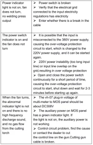
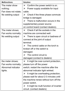
Troubleshooting the Plasma Cutter Welder Machine
Plasma Cutter Welder Machine Maintenance
Remove dust regularly with clean, compressed air. If the Plasma Cutter Welder Machine is not working in smoky conditions or heavily polluted air, remove accumulated dust daily. The compressed air pressure should be maintained at a level that does not damage small parts inside the device, max. 2-4 bar.
Regularly check the internal systems of the welder and the correctness and reliability of connections (especially equipment and parts). If you notice rust and lose the connection, remove the rust or oxide coating with sandpaper, reconnect, and tighten.
Avoid situations where water and steam can enter the device. If the welder gets wet, dry it and then check the insulation of the device (also between joints and contacts). After checking that everything is OK, you can continue working.
Recommended For Your Project
VEVOR 3 in 1 Plasma Cutter Welder Machine, CT-520 TIG/MMA Plasma Cutter Combo Machine Manual
Reviews
There are no reviews yet.