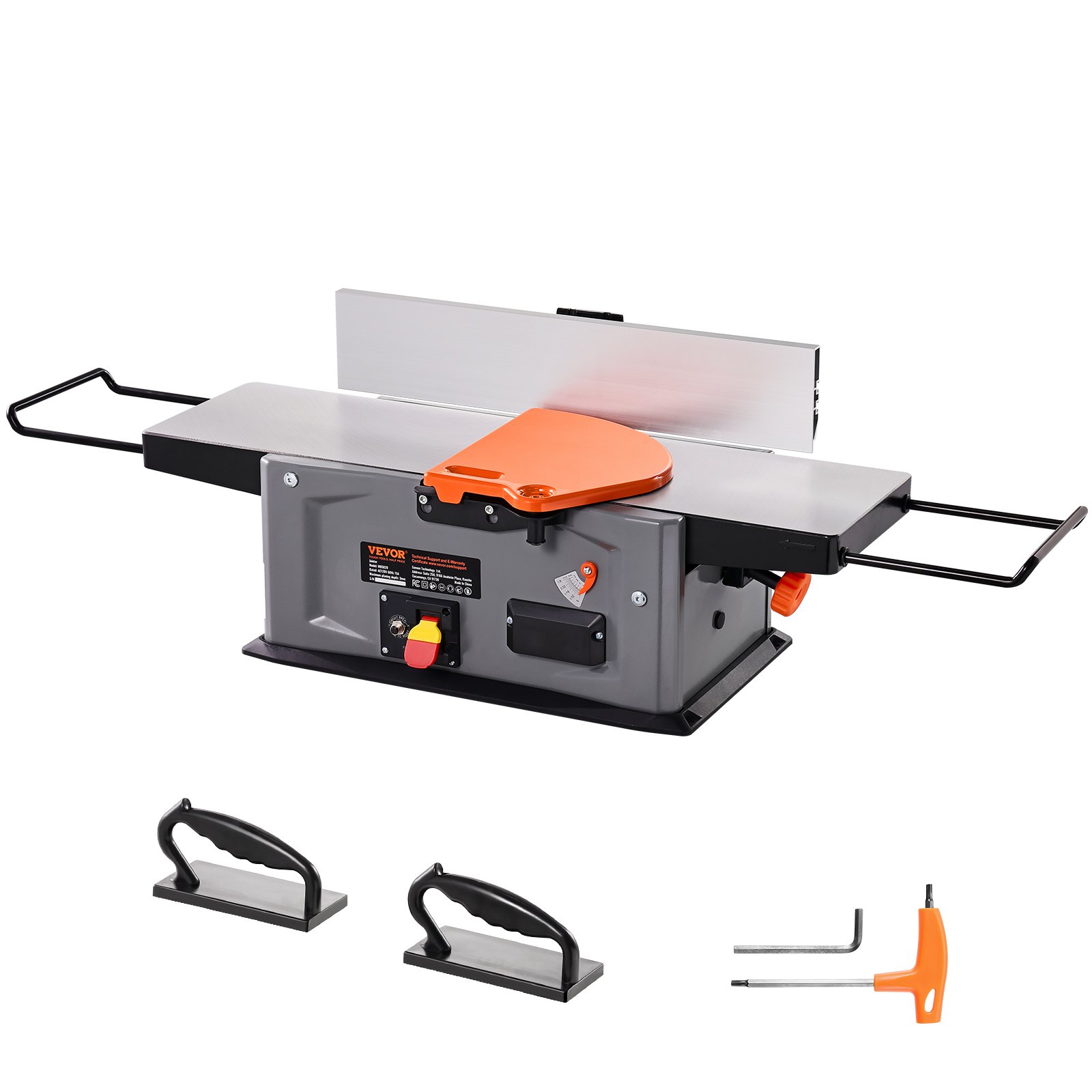
Unlock the full potential of your woodworking projects with the comprehensive VEVOR Spiral Benchtop Jointer manual. This detailed guide is designed to ensure you get the most out of your 8-Inch, 2HP 1000,0 RPM Bench Top Wood Jointer.
The manual provides step-by-step instructions for setup, troubleshooting, and optimization, making it a valuable resource for both novice and experienced woodworkers. Discover how to use the 18-Blade Spiral Cutterhead efficiently and take advantage of the extendable arm, which reaches up to 6.5 inches, and the 8×42.3-inch worktable. With an adjustable depth range of 0-1/8 inch, this manual will help you achieve precision and excellence in every cut.
Download the VEVOR Spiral Benchtop Jointer manual today and elevate your woodworking skills easily and confidently.
Spiral Benchtop Jointer Manual
Model 03200
Important Safety Precautions
- Before operating any machinery or power tool, read and understand all safety instructions in the owner’s manual for the tool or machine.
- If you do not have a manual, contact the manufacturer and obtain one before using any tool or machine.
- Always wear eye protection in compliance with ANSI safety standards when operating any power tools or machinery.
- Always use proper guards and safety devices when operating power tools and machinery.
- Carefully check router bits before each use. Do not use if damage or defect is suspected.
- Do not exceed the recommended RPM for any router bit.
- Do not wear loose clothing or jewelry that may catch on tools, machinery, or equipment.
- Unplug the spiral benchtop jointer when mounting or adjusting for mechanical performance.
Spiral Benchtop Jointer Routing Safety Precautions
- Always ensure the fence on your router table is locked firmly into position before each use.
- Never force the bit or overload the router beyond the expectations of the spiral benchtop jointer.
- Be sure that at least 3/4 of the shank length is inserted securely in the router collet.
- Never bottom out the bit in the collet. Allow 1/8” clearance between the bottom of the sink and the bottom of the collet.
- Always rout in two or more passes when large amounts of stock must be removed.
- Use reduced RPM speeds for larger diameter router bits.
Suggested Router Bit Speeds
Bit Diameter: Max. Speed
- 1” (25mm): 24,000 RPM
- 1-1/4” – 2” (30-50mm): 18,000 RPM
- 2-1/4” – 2-1/2” (55-65mm): 16,000 RPM
- 3” – 3-1/2” (75-90mm): 12,000 RPM
Spiral Benchtop Jointer Electrical Information
Grounding Instructions
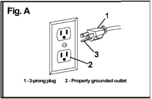
IN THE EVENT OF A MALFUNCTION OR BREAKDOWN, grounding provides the path of least resistance for electric current and reduces the risk of electric shock. This benchtop jointer has an electric cord, an equipment grounding conductor, and a grounding plug. The plug MUST be plugged into a matching outlet that is properly installed and grounded following ALL local codes and ordinances.
DO NOT MODIFY THE PLUG PROVIDED. If it will not fit the outlet, have the proper outlet installed by an electrician.
IMPROPER CONNECTION of the equipment grounding conductor can result in an electric shock. The conductor with the green insulation (with or without yellow stripes) is the equipment grounding conductor. If repair or replacement of the electric cord or plug is necessary, DO NOT connect the equipment grounding conductor to a live terminal.
CHECK with a licensed electrician or service personnel if you do not entirely understand the grounding instructions or are unsure if the tool is properly grounded. USE ONLY THREE-WIRE EXTENSION CORDS with 3-prong plugs and 3-prong outlets that accept the spiral benchtop jointer’s plug as shown in Fig. A. Repair or replace a damaged or worn cord immediately.
CAUTION: IN ALL CASES, MAKE CERTAIN THE OUTLET IN QUESTION IS PROPERLY GROUNDED. IF YOU ARE NOT SURE IF IT IS, HAVE A LICENSED ELECTRICIAN CHECK THE OUTLET.
WARNING: This router table is for indoor use only. Do not expose it to rain or use in damp locations.
Guidelines for using extension cords
Make sure your extension cord is in good condition. Using an extension cord, use one heavy enough to carry the current your product will draw. An undersized cord will cause a drop in line voltage, resulting in loss of power and overheating. The table below shows the correct size according to cord length and nameplate ampere rating. If in doubt, use the next heavier gauge. The smaller the gauge number, the heavier the cord.
Minimum Gauge for Extension Cords (AWG)
(when using 120 V only)

Be sure your extension cord is properly wired and in good condition. Always replace a damaged extension cord or have it repaired by a qualified person before using it.
Protect your extension cords from sharp objects, excessive heat, and damp areas.
Use a separate electrical circuit for your tools. This circuit must not be less than a #12 wire and should be protected with a 15 A time-delayed fuse. Before connecting the motor to the power line, ensure the switch is OFF and the electric current is rated the same as the current stamped on the motor nameplate. Running at a lower voltage will damage the motor.
WARNING: This tool must be grounded to protect the operator from electrical shock.
Installing the Router Table Fence
Place the fence on the top of the router table with the white fence faces toward the front of the router table. Align the locking knob hole with the slot on the top of the table (Fig. 1).
Insert the locking knob into the hole on the back of the fence base. Make sure the locking knob threaded shaft goes through the hole and through the slot on the table (Fig. 2).
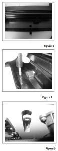
Place the hex nut into the machined slot underneath the table. Make sure the hex nut seats secure within the machined slot (Fig. 3). Align the threaded shaft of the locking with the tapped hole in the hex nut and screw the locking knob into the hex nut by turning the locking knob clockwise until tight. DO NOT OVER TIGHTEN THE LOCKING KNOB! Damage to the table slot could happen if locking knob is over tightened.
Installing the Sub-Fences
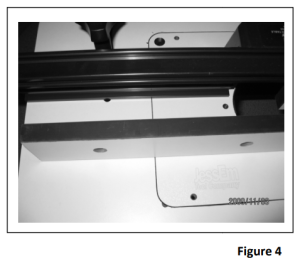
Place the sub-fence against the front of the fence extrusion (Fig. 4). Align the holes in the sub-fence with the slots in the fence extrusion.
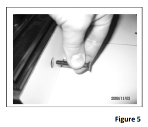
Insert the 6mm x 45mm screws through the hole in the front of the sub-fences (Fig. 5). Place the 6mm washer over the sub-fence bolt. Screw the black knob onto the sub-fence bolt. Repeat these steps for the remaining two holes. Repeat these for the other sub-fence.
Adjusting the Sub-Fences
The sub-fences can be adjusting left to right by loosening the locking knob on the back side of the fence base. Rotate the locking knob counter clockwise to loosen and clockwise to tighten the locking knob (Fig 6). With the locking knob loosen the sub-fence can slide left to right to the desired location.
Once the sub-fence has been repositioned re-tighten the locking knob before using the fence.
Installing Sub-Fence Offset Track
The router table is equipped with sub-fence offset tracks. These offset tracks are designed to be installed to allow for a 1/32” or 1/16” offset of the sub-fence. Notice the female profile of the extrusion; you will see that one side of the profile is deeper than the other side. The small side is 1/32” and the deeper side is 1/16”.
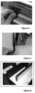
The sub-fence offset tracks are located on the backside of the fence in a specially designed storage location (Fig. 7).
Remove one side of the fence sub-fences by unscrewing the black knob and removing the sub-fence bolts (Fig. 8). Once the sub-fence has been removed, notice the end of the fence extrusion. The fence extrusion is designed with mating male profiles intended to accept the offset tracks (Fig. 9). Side the offset tracks onto the fence extrusion take care that you install both offsets on the same side (Fig. 10).
Both offsets should always be installed on the same side to insure the sub-fence is offset the same distance at the top and bottom of the sub-fence. Once the offset tracks are securely in place, reinstall the sub-fence with the sub-fence bolt, washer, and black locking knob.
Attaching the Router Bit Guard
Take the clear polycarbonate guard and two of the black knurled knobs and two 1/4” square nuts. Insert each knob through each slot in the guard and thread a square nut onto each bolt end.
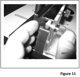
Line up the nut on the guard assembly and slide each nut into the T-slot starting from the end of the fence (Fig. 11). Then slide the guard to the center of the fence and adjust the guard slightly higher than and above the router bit. Be sure the guard clears the bit. Adjust and tighten securely before each use and after all bit changes.
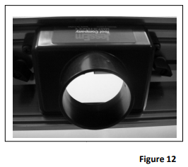
Fence Dust Port
The dust port located on the back of the fence base is designed to accept a 2-1/4” diameter and 2-1/2” diameter dust hose. The inside diameter of the dust port will accept a dust hose with an outside diameter of 2-1/4”. The outside diameter of the dust port will accept a dust hose which has an inside diameter of 2-1/2” (Fig 12).
Miter Track
The router table includes a ¾” wide miter track. This heavy-gauge aluminum extrusion is anodized in black and designed to attach jigs, hold-downs, feather boards, or a miter gauge.
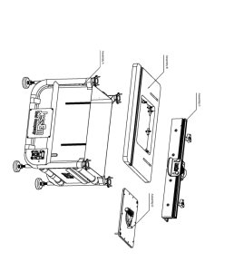
Leveling and Securing Lift and Router Plate
The Rout-R-Top has (4) corner and (4) side leveling brackets. The corner leveling brackets have (3) tapped holes. The center holes are not designed for use with the leveling screws. Only insert leveling screws into the left and right holes leaving the center hole open (Fig 13). The side leveling brackets only have (1) hole which is designed for the leveling screw.
Adjusting the plate leveling on the router plate can be made from underneath the table by inserting the hex key into the 6mm leveling screws (Fig. 14).

After adjusting the leveling screws and getting the lift plate level and flush with the table top, the router plate can be secured by inserting a bolt through the top of the plate or lift then screwing the bolt into the corresponding corner hole in the table leveling bracket. Please insure that the bolt goes through the corner hole in the plate and screws into the center hole in the leveling bracket (Fig. 15).
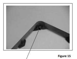
DO NOT OVER TIGHTEN!! Over-tightening will wrap or distort the top plate of the lift. This will secure the lift or plate from moving during operation.
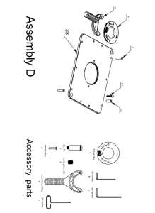
Installing the Router Plate
Your Rout-R-Plate comes with a phenolic insert ring, with a 2” diameter bit hole. Additional ring sets with different diameter pre-drilled holes and/or no pre-drilled holes are available to create your custom center-hole diameters.
Installing the TAB-LOC Insert Rings
Place the insert ring into the center hole of the router Plate (Fig. 16). With the insert wrench provided, insert the prongs of the wrench into the corresponding holes in the insert ring and turn the insert ring counterclockwise to tighten. Turn the insert wrench clockwise to loosen and remove the ring. If the insert ring becomes too tight to loosen with hand pressure, a tap clockwise on the insert wrench with a block of wood will loosen it
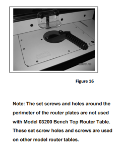
Note: The set screws and holes around the perimeter of the router plates are not used with Model 03200 Spiral Benchtop Jointer. These set screw holes and screws are used on other model router tables
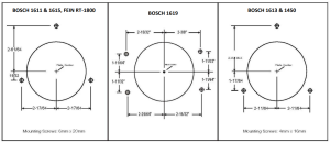
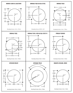
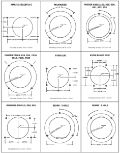
THE FOLLOWING ARE DIAGRAMS SHOWING HOLES PATTERNS FOR POPULAR ROUTERS WHICH SHOULD HELP WITH THE INSTALLATION OF THE ROUTER TO THE ROUTER PLATE:
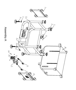
 Installing the Dust Bag and Side Storage Bags
The router table has a large canvas dust bag designed to collect the saw made from the router.
The dust bag is secured and held in place by wrapping the various Velcro straps that are attached to the bag in multiple places around the steel tubular frame. The dust bag is equipped with a front flap that can be zipped down which allows access to the front of the dust bag for making adjustments to the bottom of the router table and router motor (Fig. 17) The dust port located on the back of the dust bag is designed to accept a 2-1/4” diameter and 2–diameter dust hose. The inside diameter of the dust port will accept a dust hose with an outside diameter if 2-1/4”. The outside diameter of the dust port will accept a dust hose with an inside diameter of 2-1/2” (Fig. 18).
The router table has side storage bags attached and secured by wrapping the Velcro straps around the steel tubular supports on each side of the tubular frame. The storage bags have storage pockets on the inside of the bag that are designed to hold router bits, insert rings, and various other tools needed when operating the router table (Fig. 19).
Connecting the Power Cords
The router table is provided with two power cords. Both power cords are designed to work with a 120V, 15A power input. Power cords are connected to the on/off switch on the front of the router table. DO NOT CONNECT ANY OF THE POWER CORDS TO ANY POWER SOURCE OTHER THAN THE RECOMMENDED POWER LISTED ABOVE!
The power cord with the female connector connected to the router motor (Fig. 20). The power cord with the male connector is to be connected to a 120V, 15 A power source (Fig. 21).
Spiral Benchtop Jointer Power Cord Storage
The router table is equipped with two brackets attached to the back of the steel tubular frame that are designed for the power cord to be wrapped around during storage or transport of the router table (Fig. 22).
Power Switch (On/Off)
The router table has been equipped with an on/off power switch designed to work with any router motor that has electrical power requirements of 120V, 15A.
After properly connecting the power cords, the router motor can be turned on by lifting up on the power switch. The router motor can be turned off by pushing down on the power switch.
The power switch has a safety key that can be removed when the router table is not in use (Fig 23). Removing the safety key provides lock out protection and when removed, will not allow the motor to be turned on until the key has been replaced.
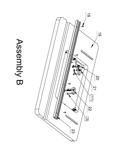
Dust Bag Hole for Power Cord
On the lower right side of the dust bag is an access hole for the router motor power cord to exit the bag (Fig 24). After installing the router, insert the router motor power cord through the access hole. Connect the female
shown in Figure 20 to the router motor power cord.
Note: The connection between the female terminal and the router motor power cord must be made outside in a dust-free environment.
Leveling the Router Table
The router table is equipped with four adjustable leveling feet. Each leveling foot can be adjusted independently.
Note: Always place the router table on a smooth, flat, and level surface to ensure safe and proper operation.
To adjust the leveling feet, turn the jam nut on the leveling foot counterclockwise to loosen the jam nut. Turning the leveling foot clockwise will allow the foot to move toward the steel tubular frame and turning the leveling foot counterclockwise wise allow the foot to move away from the steel tubular frame. Once the leveling foot is in the desired position, retighten the jam nut to secure the leveling foot in the correct position.
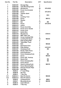
Spiral Benchtop Jointer Parts List
Recommended For Your Project
VEVOR Spiral Benchtop Jointer, 8-Inch, 2HP 1000,0 RPM Manual


Reviews
There are no reviews yet.