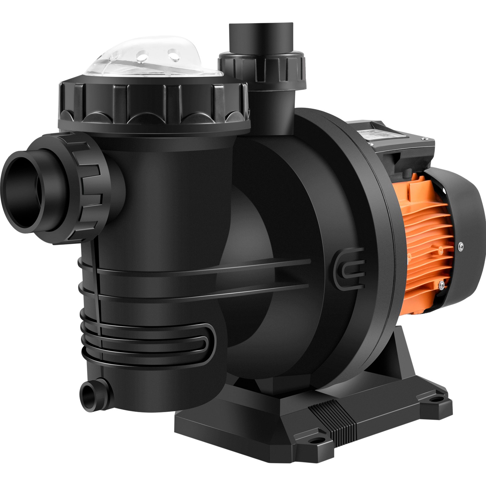
Unlock the full potential of your VEVOR Pool Pump Swimming Pool Pump 48V DC/500W Solar Water Pump with our comprehensive product manual download. This detailed guide provides you with all the necessary information to effortlessly set up, troubleshoot, and optimize your pool pump for maximum efficiency.
Whether you’re a seasoned pool owner or a first-time user, our manual includes step-by-step instructions, illustrations, and valuable tips to ensure you get the most out of your investment. From initial installation to routine maintenance, our user-friendly manual covers every aspect, making it an indispensable resource for ensuring your pool pump operates smoothly and efficiently.
Download now to have all the answers at your fingertips and enjoy a hassle-free pool experience with the VEVOR Pool Pump.
Swimming Pool Pump Installation and User Manual
USER MANUAL FOR SPS, SPSC SERIES SOLAR PUMP AND CONTROLLED BOX
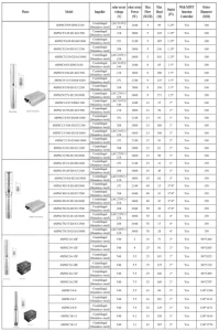
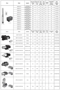
MODEL IDENTIFICATION
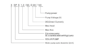
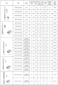
PUMP SPECIFICATION
OPERATING PRINCIPLE
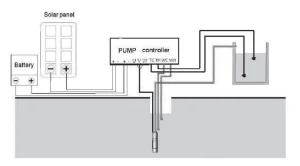
Solar photovoltaic panels convert sunlight to electrical energy, which is passed to the solar pump controller. The solar controller stabilizes the voltage and creates a three-phase output to drive the pump’s electric motor. If backup batteries (optional) are available, the controller can charge them.
The stored energy can be used later when sunlight is insufficient to drive the pump. Sensors are also connected to the controller and can protect the pump from running dry.
The pump is turned off automatically when a water tank is full. The system can be remote from traditional power sources and fully automatic with no ongoing electricity charges.
(1) Selecting the solar panel of the pumping system
If you have not purchased a complete system from your supplier, the following formulae will be helpful. Your pump supplier will be able to help you with panel selection.
- Solar PV panel (solar panel) selection:
Power of PV panels (watts) =Rated power of pump (watts) x (1.3-1.6).
Voltage of solar panel = Rated voltage of pump (volt) x 1.5
Your supplier will already match the controller to the pump.
For example, a 300-watt pump needs a minimum of 390 watts of PV panels to drive it. (300w x 1.3 = 390w)
- You may need combinations of panels, especially for larger pumps. When connecting solar panels, you have to connect them in series to reach the pump’s rated voltage and then in parallel to reach the pump’s rated current.
- Panels in parallel double the current and the wattage of the panels.
- Panels in series double the voltage and the wattage of the panels.
- Panels in series, add the voltage and the wattage of the panels.
For example, 2 x 12-volt 100-watt panels in parallel become a 12-volt 200-watt system.
2 x 12-volt 100-watt panels in series become a 24-volt 200-watt system.
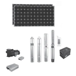
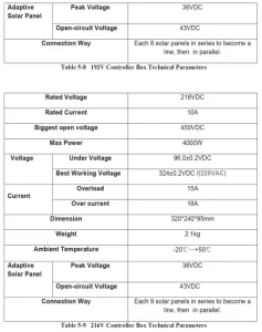
- You can select and connect solar panels as the following pictures showed:
Please note: The solar panel has a per circuit voltage of 43V. The working voltage of 36V is suitable for the pump systems of 24V and 48V.
For example:
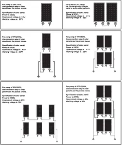
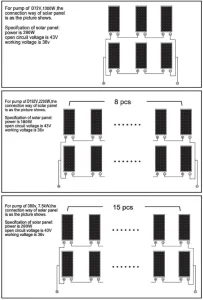
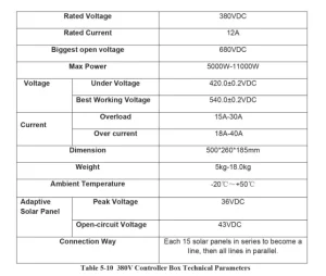
Please note: Solar panel with open circuit voltage 43, working voltage 36V is suitable for the pump system of D72V, -D216V. For example:
E.g. 2 x 12V/ 100 W panels in parallel→ 12V/200W system
2 x 12V/ 100 W panels in series- 24V/200W system.
- You can select and connect solar panels as the following pictures:
(2) Selecting the battery of the pumping system
If you want to pump water when it is not sunny, you will need to buy a battery and battery controller. Please note that if you want to add batteries, you will need an additional solar charge controller (not supplied in the kit) and double the number of PV panels. The extra PV panels are required to charge the batteries while the pump is pumping.
The cheapest option is to try to fill an elevated header tank, or if you have no elevation, locate the tank near a utility power supply so you can pump water from the tank using a mains-powered pump.
You must use deep-cycle batteries, not car batteries. Deep-cycle batteries are designed to take much lower continual discharges than regular car batteries. They normally have an amp-hour rating shown as AH, for instance, 100AH. Use the following formulas to calculate the battery size required for backup.
Please note that even with a deep-cycle battery, discharging it to a low level will shorten its life; this is why we use 60% as a discharge level.
Current drawn by the pump = pump power/voltage.
In the case of a 24-volt 300-watt pump.
300 watts divided by 24 = 12.5 amps.
2x 100AH 12-volt batteries in series, 100 Ah at 24 volts.
100Ah divided by 12.5 amps x 0.6=4.8 hours of backup.
Batteries in parallel, add the Ah, voltage stays the same.
Batteries in series, add the voltage, Ah stays the same.
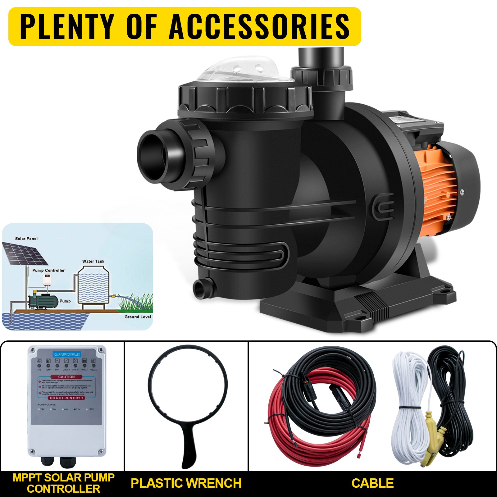
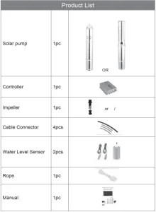
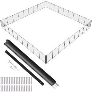
PAKING LIST
Open the package and check that all the parts have been supplied.
INSTALLATION
- Wiring the pump
Connecting a longer cable to the pump. (Pumping for lower than 50m, cable should be 3mm squared. 4mm squared cable must be used for higher than 50m.)
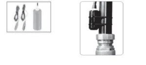
Use the parts in the cable connector kit (heat-shrink tube and tape) to connect a longer supply wire to the pump. If you don’t have a heat gun to shrink the tube, the barrel of your soldering iron will do, or you can use a butane torch, but with great care, so you don’t melt the insulation or set it on fire. Bear the insulation back as shown above.
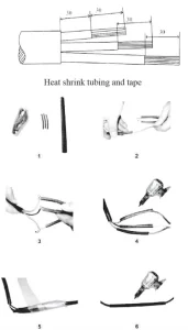
1/ Layout the components needed to make the join.
2/Place the large-diameter piece of heat shrink over the main cable and then the smaller-diameter pieces over the individual wires. Keep the heat shrink away from the joints as you solder them. Any heat transfer will prematurely shrink the heat shrink.
3&4/ Slide the small heat shrink over the soldered joints and heat using a heat gun or alternative heat source to shrink the sleeve down over the wires.
5/ Wrap the tape over the sealed joints.
6/ Finally slide the large diameter heat-shrink over the completed joint and shrink to it.
Place the pump in water before you start wiring the controller box. This will allow the pump to go through the pre-conditioning required. Do not put the pump in its final position until you have tested it, unless it is easy to see and remove.
- Solar pump control box
- Function of solar pump controller box:
- Low voltage protection (It is automatic)
- Overvoltage protection (It is automatic) c. Over current protection (It is automatic)
- Protection for low water level in the well (WC, WH sensors)
- Protection for full water level in tank (TC, TH sensors)
- Controlling the running speed of the motor (Speed regulator)
- Delay for restart working function (Timer regulator is to be set a period of rest time after the pump stops working from low water level protection in the well)
- MPPT function. (Maximum Power Point Tracking)
- Battery. (The battery can be connected to the controller directly to store electricity.)
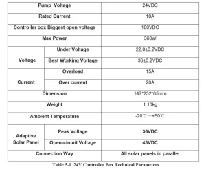
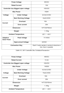
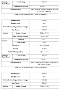
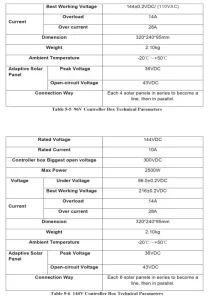
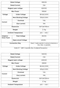
Technical parameters of the Swimming Pool Pump controller box
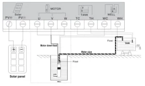
Wiring the controller box
Before you start wiring the control box, switch must be off.
1/Wire the pump and panels to the control box as per the wiring diagram below. Both the pump and the controller are labeled with “U,” “V,” and “W.” Make sure they are correspondingly connected and do not touch each other.
2/1f, if you intend to use a battery, the wiring is per the bottom diagram. Make sure the polarity is correct, connecting “to” and to Charge controllers generally have the following connections. Battery, Panel, and Load are either written or in pictorial form. The solar PV input is connected to the load terminals of the charge controller. As a safety margin, we recommend the charge controller be able to supply at least 1.5 times of the pump requirements. Basic formula, Load (amps) = pump attage/voltage. Amps x 1.5 = charge control load.
e.g. A 300 watt 24-volt pump. 300/24=15 amps. 15A x 1.5=22.5amps. The charge controller must be able to supply 22.5 amps to the load at 24 volts.
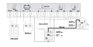
Caution. When wiring a battery, do not reverse or shorten the terminals. The reverse electrode will damage the controller. Never connect “B+” to “B—.“ It will short the terminals and bring heavy current. We advise removing all metal wrist bands or watches before you start.
A short across a metal watch strap will result in it, glowing red hot in seconds, causing severe burns. Solar PV panels can also produce a lot of energy when connected, so caution must also be exercised here. A dark cloth to shade the panels is a good precaution to reduce the power output.
3/ It is important that the water sensors are appropriately connected. The water low (WH) and water common (WC) sensors are very important because they protect the pump from running dry. Do not link out WH under any circumstances. (The only exception is for troubleshooting.) Floats can also be used instead of sensors. The installation diagram is presented as shown in the photo.
The sensor terminals TC and TH can be left disconnected if you are not using a header tank or don’t care if the water flows out on the ground once the tank is full.
SWIMMING POOL PUMP CONTROLLER
NOTE:
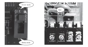
- Please connect solar panels to P+ and P-, battery to B+ and B-
- If solar panels are connected, but the battery is not connected, please switch to “solar mode.”
- If the battery is connected, please switch to “battery mode.”
- Max. voc from solar panels:
There’s a fuse to protect the controller from overvoltage; see the photo above.
Charging function OL
The charging function can only be used for the RTES50208 controller, mainly applied to a strict pump-out.
- After connecting the battery input and solar panel input, turn on the switch to the Solar Panel Mode. At first, all the lights were on, and then they went off. After 1 second, the “SYS” clock indicator system went into self-check. After the pump’s “self” indicator, the pump ran. Finally, the lights flashed MPPT, “said the system into the maximum PowerPoint algorithm.
If you need to connect the battery, turn on the switch to Battery Mode.
If no need to use the battery, turn on the switch to the Solar Panel Mode.
- The user can set the upper limit of the motherboard’s maximum output speed potentiometer. The Clockwise potentiometer motor speed decreases, and the counter-clockwise potentiometer motor speed increases.
- When the battery power is not enough, the Controller automatically switches to a rechargeable battery mode, with this “Pump” indicator, flashing lights, and “MPPT.”
This process pump is still running.
Announcements
- During the wire connection, please note that you must turn off the switch to the middle part, “STOP,” and then the power will be cut off. Make sure the solar panel input is the final step of the insertion. The right connection can avoid damage caused by a wrong operation.
- Please pay attention to the “P+” and “P—” terminals. The voltage between the “B+” terminal and “B—” terminal cannot exceed 100V, or the controller will be fatally damaged.
- Please note that the solar pump controller can only match the relevant or recommended solar pumps’ models by our company and cannot be changed to other models at will.
- When the pump starts running, please ensure it runs in the correct direction (The water would flow out from the water outlet of the pump is the right direction). The incorrect way not only makes the pumps work irregularly, but also will cause mechanical damage to the pump by long-term running.
- Water level sensor for the well:
- The old-style well water level sensor: It acts to detect the water level of the well. Once the water level is too low and the well will dry, the pump will stop pumping. During installation, the sensor connected to the terminal “WC” should installed below the sensor of terminal “WH”, sensor of terminal “WH” should be installed above the OUTLET of pump properly. The pump will stop working when the water level below the sensor connected to terminal” WH” and the pump will work again until the water level recovery above the sensor connected to terminal” WH”. When the system detects the underground water level below the “WH” probe, it will reset automatically and stop work. Until the water level above the probe, the system would delay 30 mins, and at the same time, the “WELL” light starts twinkling till the delay finish, the system moves again. At the first electrification of the system and when the water level is detected above the “WH” probe, it will run without any delay.
- The New-style float water level sensor (Substitute for “WH” “WC”): When the user chooses the new-style float water level sensor instead of the old-style sensor, please connect the two wires of the sensor to terminals “WC” and “WH” of the controller.
Attention: Please ensure the float water level sensor is vertically bound above the outlet of the solar pump or the outlet pipe. Controller introduction
Controller Introduction
- Control the pumps to pump water and monitor the system working condition
- No putting in water (electronic component away off water).
- The two-way control input terminal can be connected to sensing equipment such as a water level probe (idling protection), pressure switch, tele-equipment, etc.
- Maximum voltage:
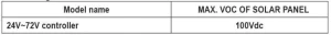
- Controller applies to 24V- 72V systems.
- Start-up requirement of system: solar panel supplies energy: >_10%
- Start-up time of motor: <_10S
- The switch can automatically switch between the charge and non-charge modes, without manual work.
- Weak power testing, when the system continuously runs 5 seconds, the actual power ≤ 10% rated power of pump, system will automatically turn into weak power, low-power light is on.
- When the system detects the water level of ground water is less than the water level probe (WH), the system automatically resets, and stops working, until the water level is higher than the water level probe (WH), the system will delay 30mins, right now Well L light starts to flicker, until finish the delay time, restart to work. When the power system is on, and detects the water level is higher than the water level probe(WH), it has no delayed time processing, and runs directly.
- It has functions such as electrode positive protection, overcurrent protection, and hyperthermia protection.
- Solar power transition system based on MPPT (Maximum power point) arithmetic.
- When the battery voltage is too low, the system automatically disconnects the power and reconnects it until the battery voltage returns to normal.
- Maximum conversion efficiency is 88% (motor and controller).
- Protection grade: IP54 (Sealed, waterproof)
- Compared with a traditional hardware start-up, a software control system start-up makes the motor start gently, and the starting current is smaller.
- Under identical current and voltage, software control increases system efficiency from 10% to 15%.
- The controller can prevent the pump from starting frequently under weak solar power by testing the dynamics of solar power. It can also protect and extend the work life of pumps.
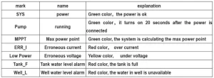
Explanation of lights and writing terminal
Explanation of lights:
TESTING THE PUMP
Before you test the pump, the controller box switch must be off.
The pump must always be under water and should have been preconditioned for at least 15 minutes. Water is the pump’s lubricant. If it is not properly ” preconditioned, ” the bearings will not be adequately lubricated. Do not attempt to test the pump even for a moment without being submerged, or permanent damage will occur. You will need a large container so the pump does not pump it dry in seconds.
- Attach a durable rope or stainless steel cable to the top of the pump using the mounting hole. Ensure the rope or cable is longer than the depth at which you want to install the pump. This is used to raise and lower the pump. Never use the power cable to do this.
- Very important! When the WH sensor is installed, attach it with a tie wrap to the pump cable so it is at least 0.5 meters above the pump body—the higher, the better. The WC sensor needs to be placed below the WH sensor.
- Connect the water line and lower the pump into the borehole, well, stream, lake, etc. Please note that the pump must be operated vertically so the bearings have no excess side thrust. Water should be clean with no corrosive materials in it. The pump must be at the correct depth. Do not put the pump any deeper than 20 meters in the water. The level can drop when water is drawn off, depending on the water source. The sensors need to be placed to account for this; otherwise, it will stop and start.
- The PV panels need to be in full sun. Turn on the control switch. The pump has a “soft start function”. It will start after 6 seconds and then spin up to full speed in the next 6 seconds. If the wiring is correct the pump will restart and the pump will run continuously. If the pump does not pump much water, it is possible its wiring is incorrect and running backwards.
- Test the sensors at a time. When pulling the “WH should stop immediately. The pump should start after sensor out of the water, the pump putting it back into water.
To test “TH” and “TC”, start the pump with sensors out of the water. Then put in water, the pump should stop. Pull the TH sensor out of the water and the pump should start again.
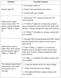
Swimming Pool Pump Troubleshooting
DOS AND DON’TS
- Do keep the pump under water at all times when operating.
- Do be careful with wiring.
- Do remove the pump if not used for a long time and wipe the screw and body. Wipe with vegetable oil.
- Make sure the pump has adequate water around it during pumping. If the sensors are activated, there will be at least a 3-minute delay between pumping sessions.
- Do put your solar PV panels in a sunny position facing true north (southern hemisphere) or true south (northern hemisphere). If the panel angle is fixed, an angle equal to your latitude will be a good compromise.
- Don’t run the pump out of the water, even momentarily. It will void the warranty.
- Don’t bypass the WH sensor except to troubleshoot.
- Don’t adjust the regulation bolt in the pump’s base. It is factory set, and adjusting it will void the warranty.
- Don’t use the pump in dirty water. Premature wear will not be covered by warranty.
- Don’t disassemble the control box. There are no user parts inside.
Limited 1-year Warranty
- The manufacturer extends only to the original consumer purchaser a limited warranty against defects in material and workmanship for a period of ONE year from the date of purchase. This warranty covers the pump, controller and sensors.
- The manufacturer or authorized factory representative will repair, or at its option replace any defective part or parts of the product free of charge. In the event of a malfunction, the purchaser must return the product to an authorized dealer/agent at their expense. The warranty is limited to the repair or replacement of the product, and the manufacturer or its dealers disclaim all liability for indirect and or consequential damages, such as any installation charges.
- The warranty does not apply when the equipment has not been installed according to the instructions, damage has occurred through abuse, carelessness, improper installation, accident of mishandling during shipment, connecting to an improper voltage, or service by anyone other than an authorized factory representative.
- A purchase receipt or invoice for proof of purchase must be presented to claim the warranty.
- All repairs not covered by warranty or outside the warranty period will be charged at standard rates.
Recommended For Your Project
VEVOR Pool Pump Swimming Pool Pump 48V DC/500W Manual


Reviews
There are no reviews yet.