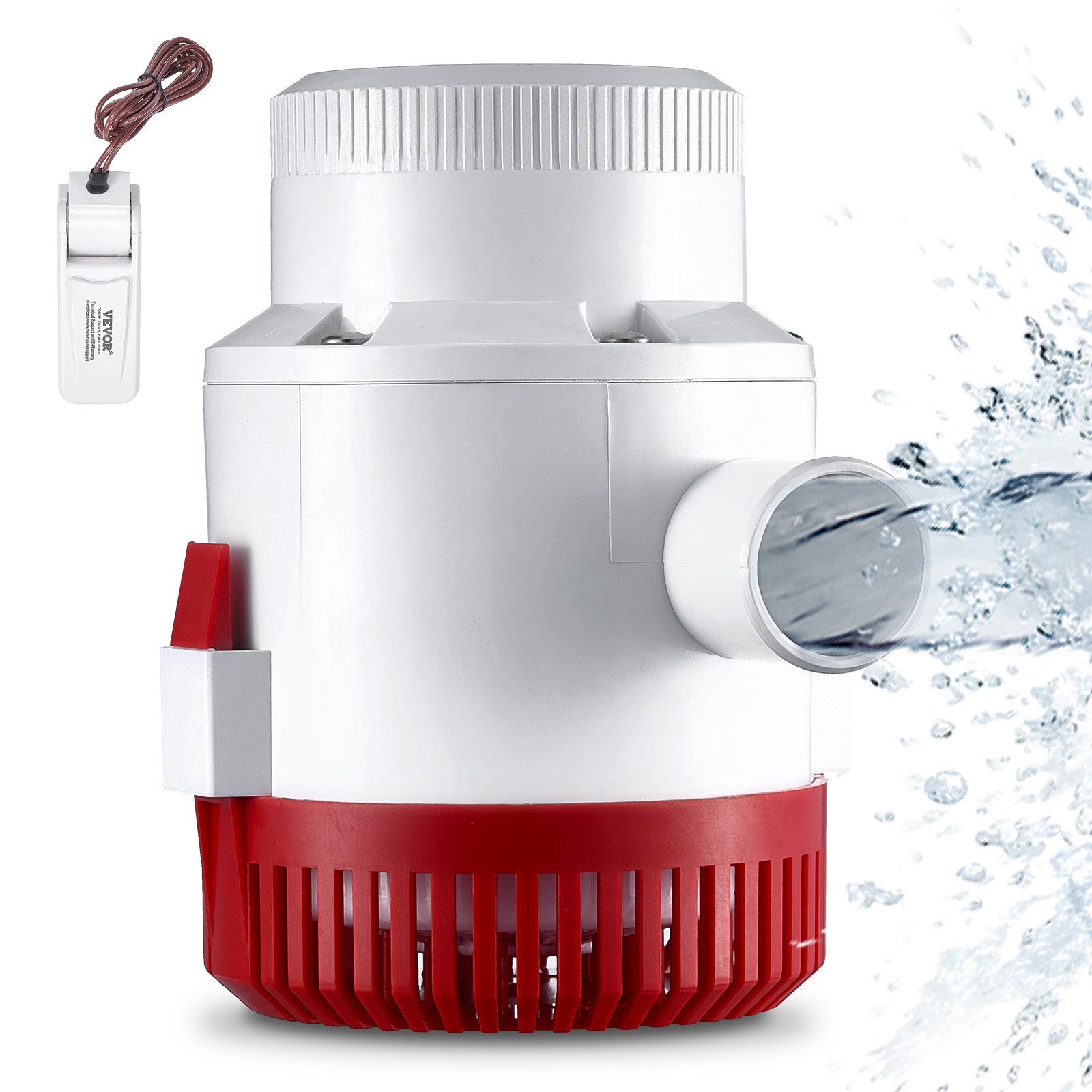
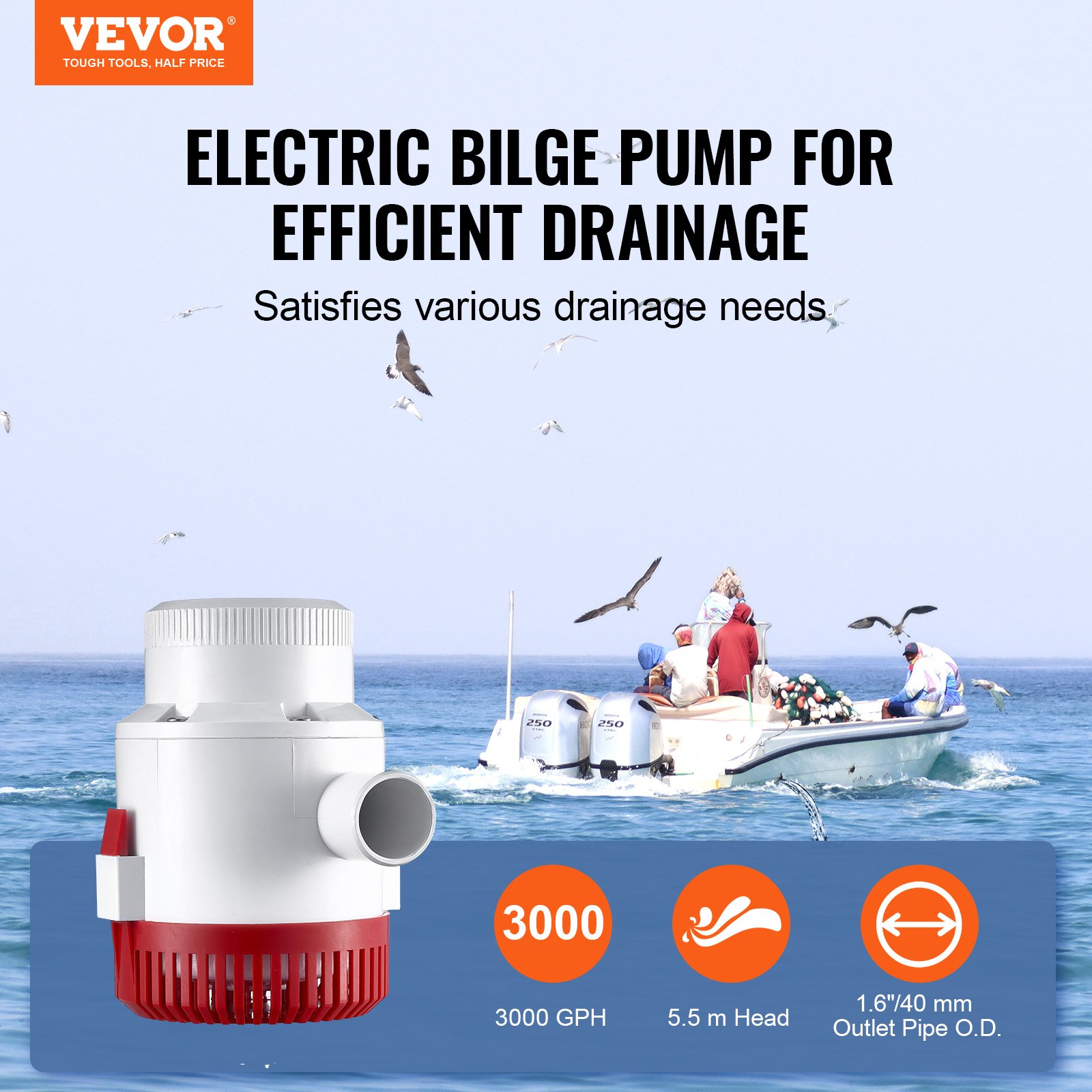

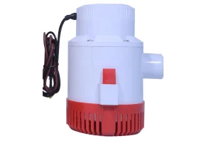
Unlock the full potential of your VEVOR Bilge Pump, 3000, GPH 12V Automatic Submersible Boat Bilge Water Pump with our comprehensive product manual. This detailed guide is designed to help you effortlessly set up, troubleshoot, and optimize your bilge pump for peak performance in any environment, whether it be on a boat, in a pond, pool, or basement. Featuring clear, step-by-step instructions, the manual covers everything from installation to maintenance, ensuring you get the most out of your marine electric bilge pump.
Our manual also includes valuable tips for using the float switch and managing the 1.6″ outlet diameter to maximize water removal efficiency. Whether you’re a seasoned boat owner or a novice, this user-friendly manual ensures your small boat bilge pump operates smoothly and reliably.
Download it today to ensure your VEVOR Bilge Pump, 3000, GPH 12V Automatic Submersible Boat Bilge Water Pump is always ready for action.
VEVOR Bilge Pump User Manual
MODEL: NMBP12-G3500-80-12
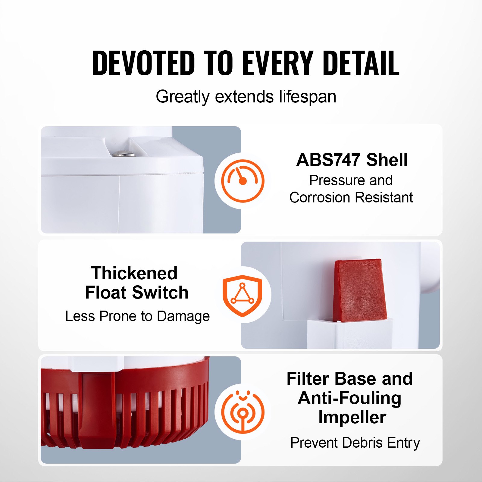
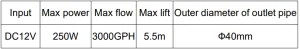
PROPERTIES OF PRODUCTS
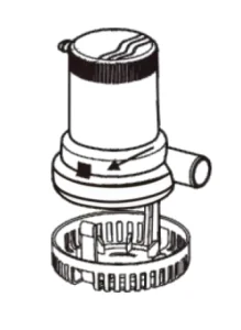
DISASSEMBLY AND USE STEPS
CAUTION: The Strainer must always be installed appropriately before attaching and running the pump.
STEP 1
Remove the strainer from the bottom of the pump by depressing the lock tabs on both sides.
STEP 2
Determine the desired location for the pump. If only one pump is used, it is usually located where the water is deepest in the bilge while the boat rests. The installation must allow for complete drainage of the hose.
All water pockets must be eliminated by having the hose running level or continuously upward.
STEP 3
Position the strainer so the pump nozzle is correctly connected to the discharge hose.
STEP 4
- If attaching the strainer to wood, fasten with stainless steel screws.
- If attaching the strainer to metal or fiberglass, first mount a wooden block and then fasten the strainer to the wooden block.
STEP 5
Mount the pump on the strainer so that both 11/2″ lock-tab snap into place. (The pump may be reversed on the setabs if so desired.)
STEP 6
Attach 1 1/8″1.D. Hose to the discharge nozzle and fasten with a stainless steel clamp. The hose(Model #80)is recommended because it will not kink when making sharp bends.
If your pump is replacing a competitive model with a hard-to-replace small-diameter hose, you may use the Adaptor Model#69 to adapt to the smaller hose.
Note: Restricting the flow from the pump by using a smaller hose does not damage the pump. However, it will reduce the flow.
STEP 7 Thru-hull Fittings
A. For most installations, install a full-size 11/8″ 1. D. Thru-hull fittingtoachieve the rated flow of the pump. Located the thru-hull fitting at least 12″ above the water line to prevent water from flowing back into the hull when the pump is off.

STEP 8 wiring
To prevent electrolysis and corroded wire connections, wire ends and terminals must be sealed with heavy-duty marine sealant and located above the highest possible water level by fastening with insulated staples or plastic straps. When installing your pump, 16-gauge wire should be used.
However, if your installation is over 20″ from the battery source, the wire size should be increased to 14 gauge.
Using a too small wire causes undesirable heat in the wires, resulting in a voltage drop and lower pump performance.
STEP 9 fusing
To protect your electrical wiring and automatic switch from possible overload, install a fuse in the battery’s positive (+) lead. If using a panel switch with a fuse holder, check to see that the proper fuse is used. You may wish to install a panel switch with a built-in holder.
STEP 10
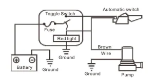
Follow one of the two wiring diagrams. Wiring for Manual. The manual system is the simplest, but it only provides ON-OFF pump control. Consequently, pumps are often left ON longer than necessary.
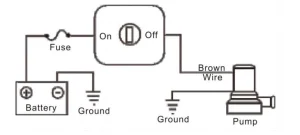
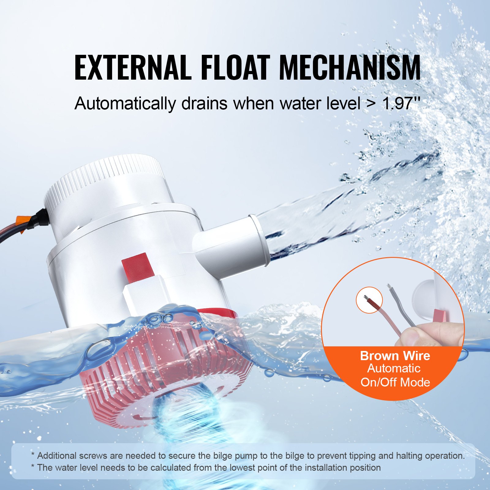
Wiring for Automatic Operation
The automatic system assures the vessel is always pumped out, even when unattended. It extends the life of the pump and your battery by automatically shutting the pump off when the water has been pumped out.
The automatic system can also provide for manual pump control by installing a panel switch. These switches have a “fail-safe” feature that automatically returns the switch to the“off” position, preventing the pump from being inadvertently left on.
STEP 11
Polarity is important. If it is not correct, the pump rotates backwards. Water will still come from the discharge nozzle, but the flow will significantly reduce. The correct polarity on the pump will be obtained when the brown wire of the pump is connected to the POS or+side of the battery.
To verify that the direction of rotation(and thus the polarity) is correct, look at the running and see if the impeller rotates in the direction of the arrow molded into the bottom.
Never insert fingers or other objects into the inlet hole.
STORAGE
The pump itself is not affected by freezing temperatures. However, if it is embedded in or surrounded by ice, it cannot be used.
Never turn the pump on if it is embedded in or surrounded by ice.
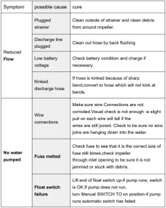
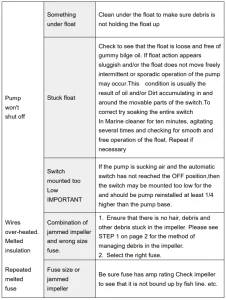
FAILURE RECOVERY
Recommended For Your Project
VEVOR Bilge Pump, 3000,GPH 12V Manual


Reviews
There are no reviews yet.