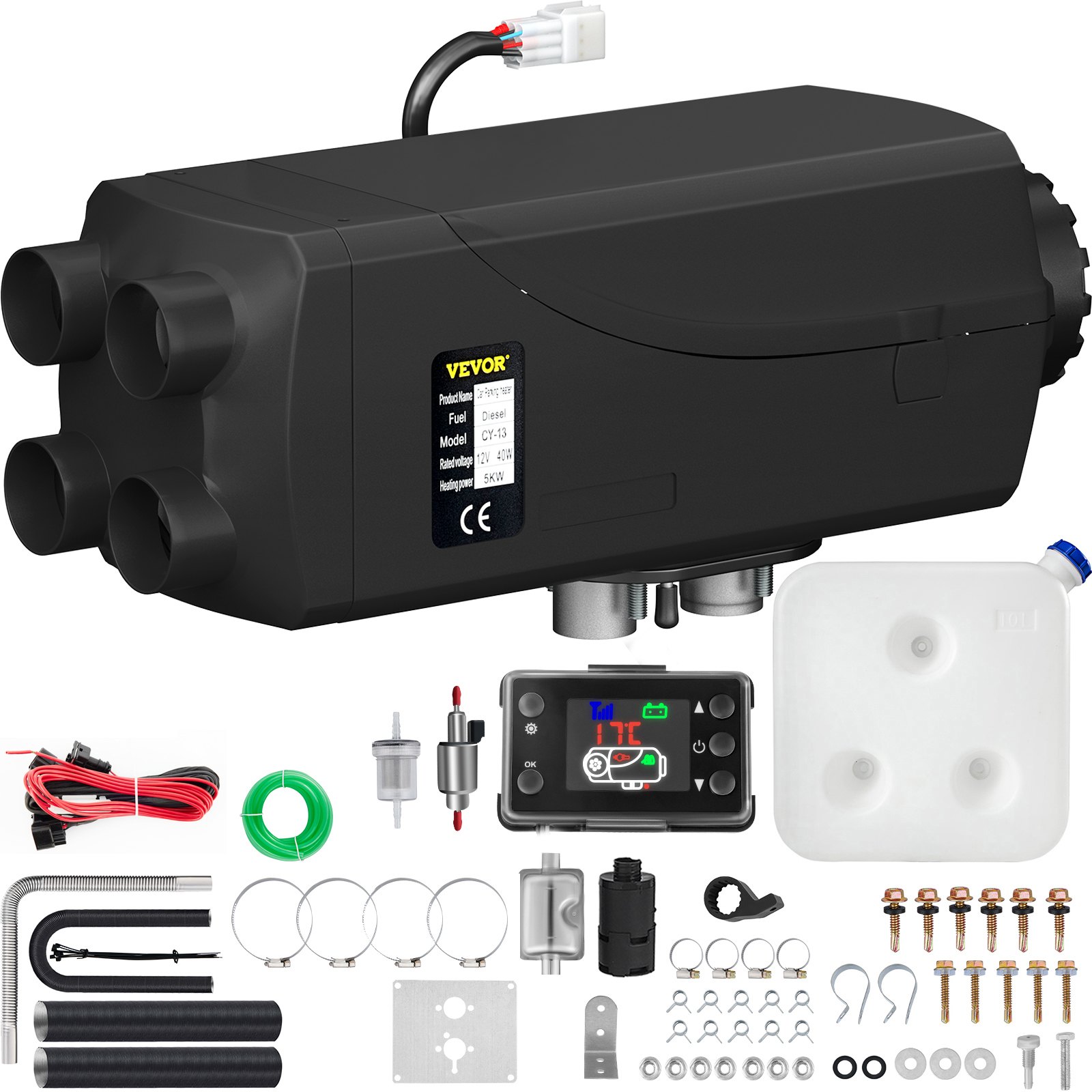


Unlock the full potential of your VEVOR 8KW Diesel Air Heater with our comprehensive product manual. Designed specifically for the VEVOR 8KW Diesel Air Heater Muffler Diesel Heater 12V 10L Tank Diesel Parking Heater 8000,W with LCD Monitor for Boat, Bus, RV, and Trailer, this manual is your ultimate guide to seamless setup, optimal operation, and efficient troubleshooting. With step-by-step instructions, clear diagrams, and valuable tips, our manual ensures you can easily install and maintain your heater, maximizing its performance and longevity. Whether you’re a seasoned technician or a first-time user, you’ll find our guide user-friendly and informative, making it an indispensable resource for anyone looking to get the most out of their VEVOR Diesel Heater. Download your manual today and experience the convenience and reliability that comes with having expert guidance at your fingertips.
VEVOR Diesel Air Heater User Manual
MODELS: KW 2.0, 5.0, 8.0
Tips
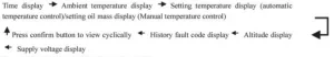
- The fuel pipe should be 1.5 meters or 2 meters.
- The voltage would be better if 11.5 V- 12.8 V.
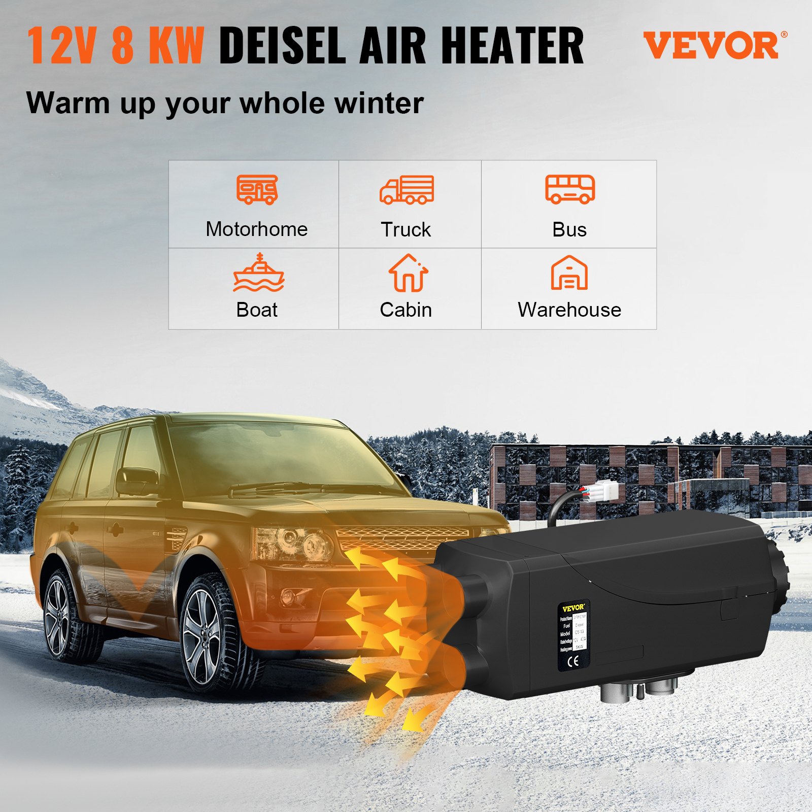
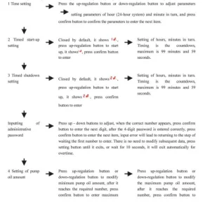
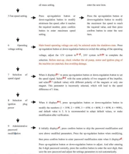
Application field of the Diesel Air Heater
The air heater is not affected by the engine and is supplied by the corresponding power for the following vehicles.
- All kinds of autos and trailers.
- Construction machinery.
- Agricultural machinery.
- Boat, ship, yacht.
- Caravan
Function
- Warm up, defrost the glass.
- Heat and keep warm for the following area:
—Driving cab, cabin
—Cargo hold
—Interior of staff carrier
—Caravan
The diesel air heater can not be used in the following places and situations
Constant heating for a long time:
- Living room, garage
- Residential purpose boat
Heat and dry:
- Life (people, animals), blowing hot air directly
- Articles and objects
- Blow hot air into the container
Diesel Air Heater Safety Instructions
Installation
Prevent the substances around the heater from being damaged and influenced by high temperature.
Exhaust emission system
When installing the exhaust vent, prevent the exhaust from entering the heating space through the ventilator, hot air inlet, and window.
Keep the exhaust pipe clear. The exhaust pipe outlet shall be kept from anything flammable, and avoid heating and igniting the flammable goods and loading cargo on the ground.
The air inlet of combustion-supporting air
The combustion-supporting air used for heater burning shall not be inhaled from the passenger compartment. The air inlet shall not be blocked, and keep the inlet shall be kept open and clear.
If the air inlet is equipped with a filter, keep the filter clean regularly.
The heating air inlet
The heated air shall be composed of fresh or circulating air, which is inhaled from a clean area.
The air inlet pipe shall be protected by a safety fence or other suitable tools, and the pipe shall be clear and open.
To prevent the people and goods from being damaged, the hot air pipe shall be installed in the place where it could not be easily.
Safety instructions
The following measures shall not be adopted:
- Change the critical component of the diesel air heater.
- Make use of the spare parts from other manufacturers without permission.
- Disobey the instructions and guide during installation or operation.
Only allow the original attachments and spare parts during installation and maintenance.
The heaters shall not be used in places where flammable vapor or dust, for example:
- Fuel depot.
- Carbon storehouse.
- Timber storehouse.
- Granary and similar sites.
- Diesel/petrol station.
The heaters shall be turned off when filling fuel.
If there is a fuel leak or discharge from the heater’s fuel system, don’t hesitate to contact the service provider for repair.
Cutting off the electric power is forbidden during the work process to stop the heater from working.
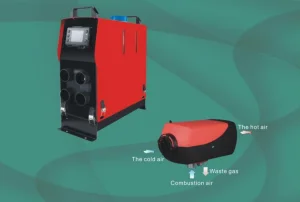
Product (Diesel Air Heater)
Survey
KW2.0 Air heater (hereinafter referred to as the heater) is independent of the original engine system, it makes use of 12V or 24V direct current to drive.
The heater has two kinds of control modes: Automatic control mode and Manual control mode.
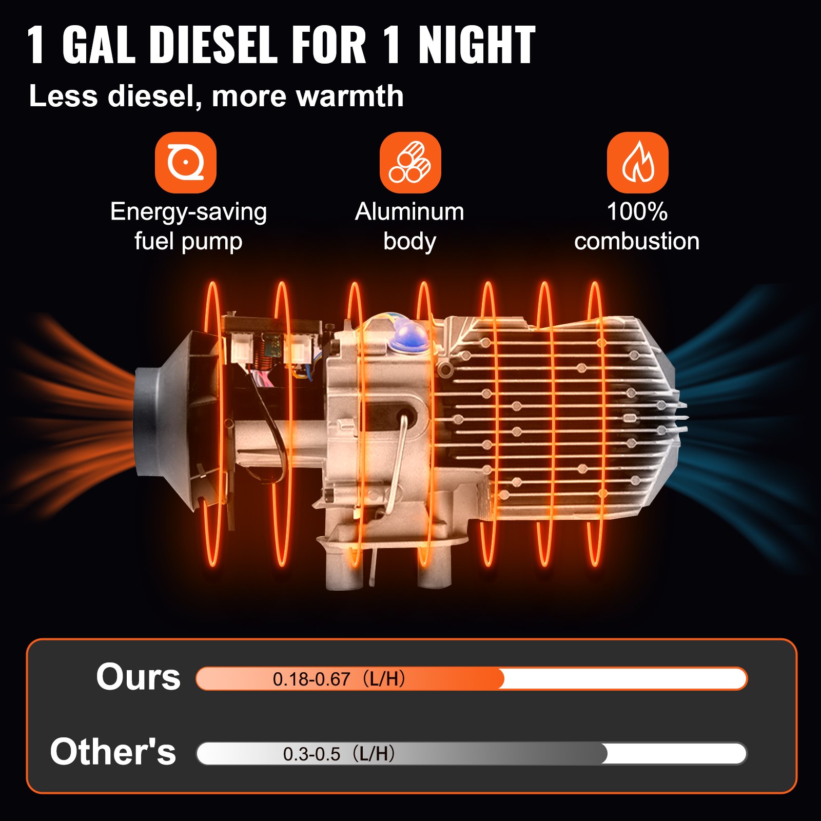
The diesel air heater adopts light diesel and gasoline, which corresponds to the environmental temperature as fuel, and it can be started and operated normally at a temperature above -40℃.
The inhaled fresh air is heated to hot air through a heat exchanger by the energy that comes from fuel burning, then blown to where it is needed. This type of heater owns the advantage of compact structure, light weight, high thermal efficiency, economize on electricity and fuel, and easy installation.
Diesel Air Heater Technical specifications
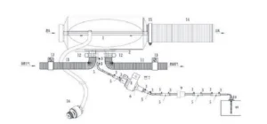
Structural Principle
After the heater starts, the glow plug comes into operation, the magnetic pump supplies fuel, and the combustion-supporting fan inhales combustion-supporting air from outside the car.
The fuel generates heat by burning in the combustion chamber, which the aluminum heat exchanger takes.
The inner air pushed by the heat exchange fan brings heat to where it is needed through the surface of the heat exchanger, and the combustion emission is discharged through the exhaust pipe.
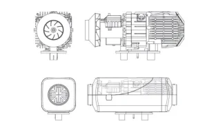
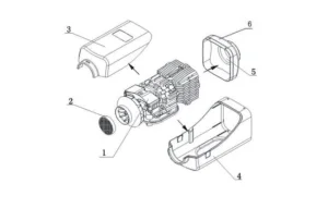
The structure of the hood-shaped case:
Installation of Fuel Supply System
Fuel for the diesel air heater can be supplied from the vehicle’s fuel tank or an additional independent fuel tank. It is not allowed to install the fuel tank in the cab or passenger compartment or any region that is possibly to cause fire if an independent fuel tank is used.
The elevation difference between the air heater and fuel pump, and between the fuel pump and the fuel pump, produces pressure from fuel to the fuel pump. The inner diameter and length of the fuel tube is related to the resistance of the fuel route. Please consider such factors for installation.
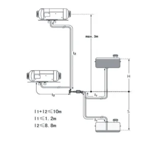
Diesel Air Heater Fuel pump installation
The fuel pump should be installed in places that can avoid heat radiation from the vehicle parts emitting heat, and in areas with cool air. Its ambient temperature should not exceed 20 °C.
Directions for the installation of the fuel pump are shown in the following picture.
When installing the fuel pump, please use the fuel pump holder supplied with the heater to hold the pump tight. The pump is fixed with the shock-reducing tightening piece.
Fuel Filter installation
The fuel filter should be installed before the fuel inlet port. Please make sure that the fuel flow is followed correctly. Its position shall conform with the above picture.
Installation of Fuel Tube
Only the flexible nylon tube, good light-resistance and thermal stability, supplied with the heater can be used as the fuel tube. The inner diameter of the tube is 1’ 2mm.
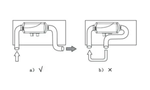
The position of the fuel tube should be away from flying stones and from any heat-emitting parts of the vehicle. A protective device can be installed if necessary. The fuel tube from the fuel pump to the main heater should be in any direction other than downward.
The fuel tube shall be tied in a proper location to make it fixed. The distance between two ties shall be less than 50cm. The fuel tube fittings supplied with the heater should be used for connections between fuel tube and fuel pump, fuel tube and heater, fuel tube and sucking tube of fuel tank and fuel tube and the fuel pump, the fuel tube and the heater, the fuel tube and the sucking tube of the fuel tank, and the fuel tube and the reducing. The fuel tube should tie with fuel tube clamps. Bubbles should be eliminated from the connecting places.
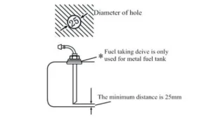
Installation of Fuel Taking Device
The openings on the fuel tank (or tank cover)for installation should be appropriate in size, with a trimmed brim and good evenness around the opening.
Good sealing is necessary for the base of the fuel taking tube. The bottom end of the fuel taking tube should be 30mm-40mm from the bottom of the fuel tank to suck enough fuel, and at the same time to avoid sucking in impurities and sediment on the bottom of the fuel tank.
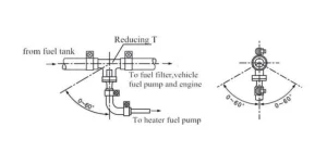
If fuel is taken from the fuel pipe to the engine, the fuel pipe from the fuel tank to the fuel filter should be disconnected and re-connected with the thicker pipes of the reducing T.And the thinner pipe of the reducing T should connect the fuel pump of the heater via fuel tube fitting and tube. The installation angle must conform to the following picture, or the normal work of the diesel air heater will be affected.
After installation, the vehicle engine shall be started and then turned off after one minuteô s work to eliminate air trapped in the fuel sucking pipe.
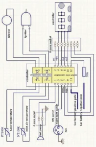
Installation of Electrical System
Installation of Combustion Supporting Air Sucking Tube and Exhaust Discharge Tube
The combustion-supporting air must be sucked in from external fresh air outside the vehicle. The exhaust from combustion must be discharged into the air through an exhaust tube. Measures must be taken to prevent exhaust from re-entering the vehicle.
The tubes go through the outer wall or holes on the bottom of the vehicle. Measures must be taken to prevent the entry of splashwater. The tubes must be protected and can resist shock permanently.
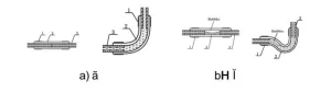
Only the air inlet and exhaust tubes provided with the heater can be used. The air inlet tube is a corrugateþipe made of an aluminum tube whose it’s surface is covered by plastic and paper. The exhaust tube is a corrugated stainless steel tube. Please identify them and do not make mistakes during installation. To connect them with the heater, please use the supplied clamps to fix them tightly on the combustion supporting air inlet and exhaust tube vent, respectively.
The protective hood on the air inlet tube and exhaust tube vents must be kept in good condition. Do not damage them or remove them.
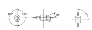
The air inlet tube and the exhaust tube should come outwards and downwards from the heater; a 4mm hole shall be prepared at the bottom of the tube to discharge condensation water. If the tube needs to be curved, the radius cannot be smaller than 50mm. Also, each tube’s sum of all curve angles shall not exceed 270N.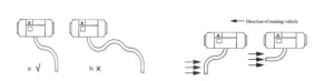
The opening of the tubes should not be opposite to the direction of the running vehicle.
The tube openings should not be blocked by slurry, rain, snow, or other dirt.
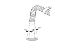
The exhaust tube should be installed far from the plastic parts or other objects with poor thermal resistance of the vehicle body.The exhaust tube should be fixed appropriately. The exhaust vent should be downwards, perpendicular to the road surface with an angle of 90£ 10£ . To ensure such an angle, the fixing clip for the exhaust tube should be 150mm from the tube end.
Warning: Violation of the above requirements may cause fire.
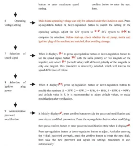
Diesel Air Heater Operation and Control
After the installation, the diesel air heater shall be turned on repeatedly for a few times to make the fuel tube full-filled, so as to avoid staring failure due to a lack of fuel.
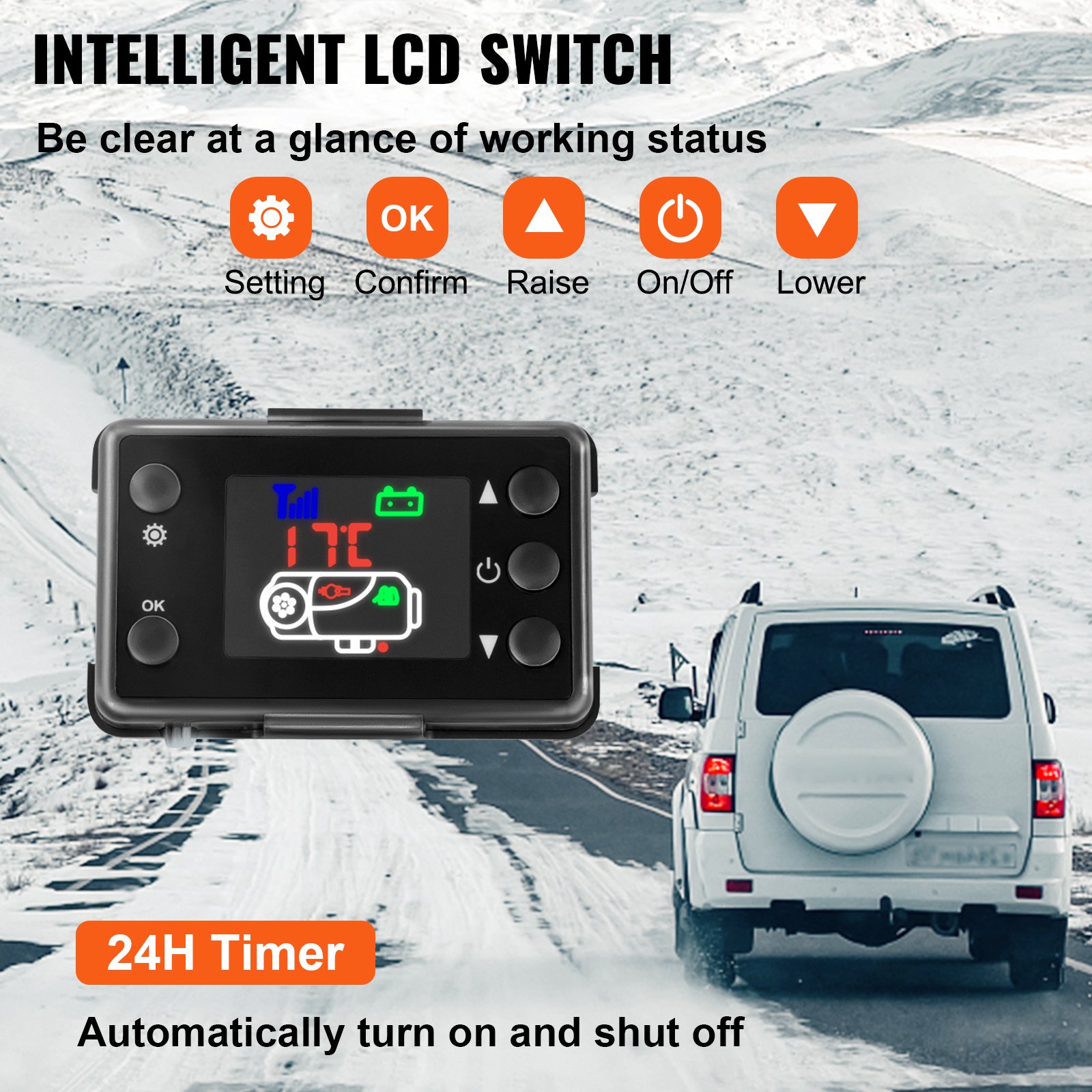
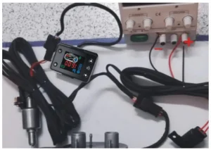
Controller
Rotary Knob Panel Instructions

Introduction of keys
ON->startup
OFF-> shutdown
Rotary knob->temperature adjustment and wind speed control
Lighting instructions:
Considering that there is lighting below the ON/OFF key, the operators will find the rotary knob easily in a dark environment.
The lighting on the outside of the rotary knob will show the temperature value and failure state.
Key function introduction
ON->Please press the ON key gently when the working voltage has satisfied the related conditions.
OFF-> Please press the OFF key gently when the diesel air heater is working.
Rotary knob->the temperature will rise when the rotary knob is rotated clockwise; at this moment, the red indicators will increase on the outside of the rotary knob. The temperature will go down when the rotary knob is rotated anti-clockwise; at this moment, the red indicators will be reduced on the outside of the rotary knob.
Fuel filling by hand
Please rotate the rotary knob clockwise under the OFF state until the red indicators are on, then, please press the OFF button for more than 3 seconds; at this moment, the manual oil pumping will be started. Please press the OFF.
Installing a picture:
Diesel Air Heater Maintenance
During the heater’s running, it tests and checks the operating state and faults throughout the whole course, and the controller constantly shows fault codes on the LCD / LED.
The fault code of the LCD screen
12V-24V Common Digital Panel Operation Instruction
Indicators
- Status-> Permanently on upon startup, blinking upon the initialization of shutdown, off upon the completion of shutdown.
- Time-> Permanently when displaying the time, setting the timed startup or shutdown, and off under other statuses.
- Voltage-> Permanently on when displaying voltage or setting the parameters with voltage, and off under other statuses
- Temperature-> Permanently on when displaying the ambient temperature or setting the operating temperature, and off under other statuses.
Key Function
- ▲-> Under the setting status, press it to raise the parameter to be set; under the non-setting status, press it to raise the operating temperature to be set.
- Set-> Enter the setting status to adjust parameters and change the machine’s operating status.
- On/off -> Promptly press it to start up the machine, and the status indicator becomes permanently on; press and hold the key for 2 seconds to shut down the diesel air heater, and the status indicator blinks.
- OK-> Under the setting status, press it to confirm the current setting value and proceed to the next parameter to be set; under the non-setting status, press it to view the machine’s status.
- ▼-> Under the setting status, press it to reduce the parameter to be set; under the non-setting status, press it to reduce the operating temperature to be set.
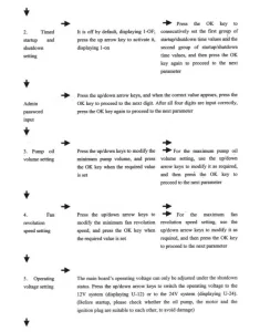
Description of Setting Parameters (Press the Set Key to Enter)
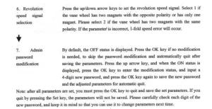
Note: after all parameters are set, you must press the OK key to quit and save the set parameters. The parameters will not be saved if you quit by pressing the Set key. Please carefully check each digit of the new password, and keep it in mind so you can use it to change parameters next time.
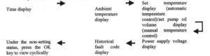
Description of the Diesel air heater’s Status Query
Manual Fuel Filling Description
Under the non-setting status, press and hold the down arrow key, then press the OK key simultaneously to enter the mánual oil pumping interface. When H-OF is displayed, first release the OK key, and then release the down arrow key.
Press the up arrow key to activate manual oil pumping. H-ON will be displayed, and you will hear the oil pumping noise. Press the down arrow key or the Set key to deactivate it and quit the manual oil pumping.
Timed Startup/Shutdown Description
After setting the run time, press the OK key to enter the timed startup/shutdown setting function. By default, OF indicates the off status, and please press the up arrow key to activate the ON status. You can press the OK key to set the first group of values, with the hour and minute values for the startup to be set first, and secondly, enter and set the hour and minute values for the shutdown if the values for the startup are set.
Then, press the OK key to enter the second group of values, with similar setting measures as those of the first group. You may specify an interval between the two groups of values. The timing function can only be performed once upon each setting, i.e. if the set timing values are performed, they will be invalid, and you need to reactivate the timing function and set new values for the timing.
Temperature Control Mode Switchover Description
Under the non-setting status, press and hold the up arrow key first, then press the Set key simultaneously.
If the panel displays P-xx (xx indicates pump oil volume), it indicates that you have entered the manual temperature control mode. The pump oil volume for operation is restrained within a range between the current and initial pump oil volume.
When you press the keys as mentioned above simultaneously and the panel displays xx °C (xx indicates temperature value), it suggests that you have entered the automatic temperature control mode and the pump oil volume for operation is restrained within a range between the maximum pump oil volume and the initial pump oil volume.
Under the two modes, the automatic changes of pump oil volume depend on the temperature variation. Still, the difference between the two modes is that, under the automatic mode, the pump oil volume can reach the maximum value set for the parameter, which leads to higher temperature of the machine; under the manual mode, the pump oil volume is limited to the current setting value and can not reach the maximum value set for the parameter, thus the equipment’s temperature is limited to the selected range, which is more adaptable to specific old-fashioned drivers.
The instructions on the LCD panel
In the condition of not setting, press the raise first, press the confirmation key simultaneously, to keep for more than 3 seconds. Remote control to the code into the interface, display HFA-, press on the remote control to open fire away Control code, the code after the exit of the code interface, the machine into the boot state, if the code does not enter the boot failure state. The timeout is wrong code, automatically withdraw from the code.

Instructions for Use of 12V – 24V General LCD Panel
Button function
- ► > In the setting state, increase the setting parameter; in the non-setting state, increase the working temperature or oil mass.
- ON/OFF -> Short press start-up button, LCD screen displays ON, and long press shutdown button for 3 seconds, LCD screen displays OFF.
- ►-> In setting state, decrease the setting parameters; in non-setting state, decrease working temperature or oil mass. The basic operation can be referred to in the above state, and the following operation descriptions can be used for settings.
- Setting -> Enter the setting state, adjust setting parameters, and change the working status of the machine
- Confirm -> Under the setting state, confirm the current setting value and enter the next parameter setting. View the machine state in the non-setting state.
Query machine status
(Keep pressing the confirm button to switch one state at a time to make it display cyclically)
Description of fuel filling in manual mode
Under the shutdown state, press the down-regulation button and the setting button simultaneously to conduct filling manually, which displays H of, and after releasing, press the up-regulation button. It displays H of the oil pump starts to work.
You can hear the oil pump working, and the oil pump icon lights up. Press the down-regulation button to display H oF, exit fuel filling, and the oil pump icon disappears. The process of line evacuation shall be done under watch. When the oil reaches the position of the oil inlet of the machine, it can be stopped. If too much oil enters the machine, there will be black smoke when igniting.
Description of temperature control mode switching
Press the up-regulation button and confirm button simultaneously to conduct the temperature control mode switch. There are manual temperature control modes (oil mass adjustment t shows P-15, number represents the oil mass) and automatic temperature control modes (temperature adjustment shows 25°, number represents the temperature).
The difference between two modes is that: in automatic mode, pump oil amount can reach the maximum upon parameter setting and the machine heat is higher, the manual pump oil amount is limited to the current setting value and will not reach the maximum oil value set by the parameter, which makes gears clearly shown and is very convenient for the part old hands.
Description of remote control code matching
In the shutdown state, press the power and confirm buttons simultaneously on the remote control first. The text ” waiting for matching appears on the remote control, then keep pressing the up-regulation and down-regulation buttons of the LCD panel.
When showing HFR, it enters the remote control code matching interface. Upon success, it will automatically exit the interface, then it shows normal working parameters. If the code matching failed, it would not enter the normal state of displaying working parameters.
The code matching state will be automatically exited when it does not receive remote control code for a long time.
Description of parameter setting procedure
(Press the setting button to enter the setting state)
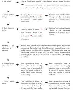
 Precautions: For clock time, set the start-up and shutdown times, and they will take effect immediately after setting them. After setting all parameters after the administrator’s password, you must press the confirm button until item 9 to exit, through which we could save the set parameters.
If quitting midway, previous adjustment data will be lost and invalid. Please check each new digit of the password carefully and save it, through which you can enter in the parameter modification next time.
Instructions for Use of 12V – 24V General LCD Panel
Button function
- ->In non-setting state, increase the working temperature or oil mass. In the setting state, increase the setting parameter.
- On/Off->. Long press for 3 seconds to start-up, the screen displays, and long press 3 seconds to shutdown, the screen displays off
- -> In non-setting state, decrease the working temperature or oil mass. The above state is sufficient for the basic operation of decreasing the setting parameters in the setting state. Other operations are described as follows.
- Parameter settings -> Press the up-regulation button for a long time to enter the setting state. The parameters can be adjusted to change the working status of the machine.
- In the parameter confirmation -> setting state, confirm the current setting value by pressing On/Off button to enter the next parameter setting. Press the On/Off button to view the machine’s running state in the non-setting state.
- Remote control code matching -> Press the down-regulation button for a long time to enter the remote control pairing state, and press remote control power button for pairing. Please refer to the description later for detailed operation.
- Temperature control conversion -> Switch the temperature control mode by simultaneously pressing and holding the up-regulation and On/Off buttons. Please refer to the following description for details.
- Fuel filling -> Press and hold down-regulation button and On/Off button simultaneously to start the fuel filling function, as described later.
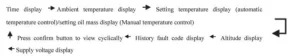
Query machine status (keep pressing the On/Off button to switch one state at a time to make it display cyclically)
Description of fuel filling in manual mode
Under the shutdown state, press the down-regulation button and On/Off button simultaneously to conduct fuel filling manually, which displays oF, and after releasing, press the up-regulation button. It displays H oF, and the oil pump starts to work. You can hear the oil pump working, and the oil pump icon lights up. Press the down-regulation button to display H oF, exit fuel filling, the oil pump icon disappears.
The process of line air evacuation shall be done under watch, when the oil reaches the position of the oil inlet of the machine, it can be stopped. If there is too much oil enters the machine, there will be black smoke when igniting.
Description of temperature control mode switching
Press the up-regulation button and On/Off button simultaneously to conduct the temperature control mode switch. There are manual temperature control mode (oil mass adjustment t shows P-15, number represents the oil mass) and automatic temperature control mode (temperature adjustment shows 25°C, number represents the temperature). The difference between two modes is that: in automatic mode, pump oil amount can reach the maximum upon parameter setting and the machine heat is higher, the manual pump oil amount is limited to the current setting value and will not reach the maximum oil value set by the parameter, which makes gears clearly shown and is very convenient for the part old hands.
Description of remote control code matching
In the shutdown state, long-press the LCD panel down-regulation button. Enter the remote control code matching interface to make it display FR-, then press the On button of the remote control to transmit the remote control code, and successful code matching will make it automatically exit the code interface.
If the code matching fails, it will not enter the start-up state. The code matching state will be automatically exited when it does not receive remote control code for a long time.
Description of parameter setting procedure
(Press the up-regulation button to enter the setting state)
 Precautions: For clock time, set the start-up and shutdown times, and it will take effect immediately after setting them. After setting all parameters after the administrator’s password, you must press the confirm button until to item 9 to exit, through which we can save the set parameters. If quitting midway, previous adjustment data will be lost and invalid.
Please carefully check each new password digit and save it, so you can enter the parameter modification next time.
Diesel Air Heater Main Board Fault Code Description
Bi-directional Remote Control Operation Instructions
Remote control pairing operation
In the shutdown state, first long-press the down-regulation button on the LCD panel that needs to be paired first. Showing HFR means it enters the remote control code matching interface.
Then press the power button and confirm button on the remote control at the same time, the text ” waiting ” appears on the remote control, and the remote control and switch enter the automatic matching process. After successful code matching, it will automatically exit the code interface and display the normal working parameters.
If the code matching failed, it would not enter the normal state of displaying working parameters. The code matching state will be automatically exited when it does not receive remote control code over time.
Temperature control mode switching
When the temperature control mode is selected by remote control, only press the up-regulation and down-regulation buttons simultaneously to display the temperature when switching to automatic temperature control, and the oil mass will be displayed if the temperature is controlled manually.
Working status adjustment
The working status of the heater can be adjusted at any time by remote control. The methods are as follows:
- Up-regulation button: Increase the pump oil amount (manual temperature control mode) or raise the setting temperature to increase the output temperature of the heater.
- Down-regulation button: Decrease the pump oil amount (manual temperature control mode) or reduce the setting temperature to decrease the output temperature of the heater.
Instructions for the use of the bi-directional remote control receiving
Introduction of buttons:
On/Off->long press On/Off
Lighting instructions
Light is under the switch button; long lighting indicates the start-up, and flashing suggests a fault. Introduction of button functions
Start-up-> When the operating voltage meets the conditions, press ON/OFF for a long time.
Fuel filling in manual mode
In shutdown state, start the manual oil pumping by pressing On/off button 5 times continuously and quickly. Please gently press the On/Off button to stop the oil pumping when the air is removed from the oil circuit.
This process requires observation of a specially-assigned person to avoid excessive fuel entering the machine and black smoke at start-up.
Remote control pairing
In the start-up state, press On/Off button 5 times continuously and quickly, the indicator light flashing means it has entered the remote control pairing waiting state. At the same time, press the power button + setting button on the remote control for a long time to start the remote control pairing. Wait for auto-completion of pairing to exit.
Bi-directional Remote Control Operation Instructions
Operation instructions for buttons
- On/Off button: Press and hold for 2 seconds to turn on, or turn off
- Confirm button: View the host working status
- Up-regulation button: Increase the oil mass or temperature according to the temperature control method.
- Down-regulation button: Increase the oil mass or temperature according to the temperature control method.
Remote control pairing operation
First, the receiving part, which needs to be paired, is put into the waiting pairing state. Then press the power and confirm buttons on the remote control simultaneously, and the interface of waiting for pairing appears on the remote control.
The remote control and the switch enter the automatic pairing process. The code matching interface will be automatically exited after the successful code matching, and the normal working parameters will be displayed. If the code matching failed, it would not enter the normal state of displaying working parameters. The code matching state will be automatically exited when it does not receive remote control code over time.
Temperature control mode switching
When the temperature control mode is selected by remote control, only press the up-regulation and down-regulation buttons simultaneously to display the temperature when switching to automatic temperature control, and the oil mass will be displayed if the temperature is controlled manually.
Working status adjustment
The working status of the heater can be adjusted at any time by remote control. The methods are as follows: Increase the pump oil amount (manual temperature control mode) by using the up-regulation button, or raise the setting temperature to increase the output temperature of the heater.
Decrease the of pump oil (manual temperature control mode) by using the down-regulation button or reduce the setting temperature to decrease the output temperature of the heater.
Instructions for Use of 12V – 24V General LCD Panel
Button function
- Setting -> Enter the setting state, adjust the setting parameters, and change the working status of the machine
- Confirm -> OK -> Under the setting state, confirm the current setting value and enter the next parameter setting. View the machine state in the non-setting state.
- ▲-> In the setting state, increase the setting parameter; in the non-setting state, increase the set working temperature.
- On/Off-> Short-press the button to turn on; the status indicator light will always be on. Long-press the button to turn off for 2 seconds, and the status indicator light will flash.
- ▼-> In the setting state, decrease the setting parameter, and lower the set working temperature in the non-setting state.
Description of remote control code matching
In a non-setting state, press the up-regulation button first and press the confirm button simultaneously for more than 3 seconds.
Entering the remote control code matching interface, it displays HFA-. Press the open button on the remote control to transmit the remote control code, exit the code interface after code matching, and the machine enters the start-up state.
The machine will not enter the start-up state if the code matching fails. It will exit the code-matching state after overtime code-matching work.
Description of setting parameters
(Press the setting button to enter, and the status icon corresponding to the display screen is lit)
 Precautions: After all the parameters are set, you must press the confirm button to exit before saving the settings. The parameters will not be stored if you press the confirm button to exit.
Please carefully check and save each new password digit, which you can enter into the parameter modification next time.
Query the machine status description.
Description of fuel filling in manual mode
In the non-setting state, press the down-regulation button first and then the confirm button to enter the manual pump interface. When it displays H-of, release the confirm button first and then release the down-regulation button.
Press the up-regulation button to start the manual pump oil, and it displays the H-on. You can hear the working sound of the oil pump, and the oil pump icon lit. Press the down-regulation or setting buttons to close and exit the manual pump, and the oil pump icon disappears.
Timing switch description
After the running time is set, press confirm button to enter the timing switch function setting, which defaults to “of” off state, press up-regulation button to start “on” state, press confirm button to set the first group about the hours and minutes of start-up time, and then enter the setting of hours and minutes of shutdown time after confirmation.
Press the confirm button to enter the second group. The setting method is the same as above. Set the hours and minutes of start-up time, then the hours and minutes of shutdown time.
A time interval may be set between the two sets of timings. The timing function is only run once. After this time, the current timing will be turned off. Please turn it on again and set the time for the next time. The alarm clock icon lit up after the timing setting and disappeared at the end of the timing.
Description of temperature control mode switching
In the non-setting state, press and hold the up-regulation button first and then press the setting button to display P-x.x (xx represents the pump oil amount), i.e., entering the manual temperature control mode.
The pump oil amount is limited to the current setting, which is the initial amount. When you press the 2 button above, XX is displayed. C (xx stands for temperature value), the automatic temperature control mode is entered, and the pump oil amount is controlled to run between the maximum pump oil amount and the initial pump oil amount.
The automatic change of the pump oil amount in two modes depends on the temperature change. The difference between the two modes is that the pump oil amount in automatic mode can reach the maximum value in the parameter setting, and the machine’s heat is high.
The pump oil amount in manual mode is limited to the current setting value and will not reach the maximum value in the parameter setting. The diesel air heater is limited to the range of choice, taking into account the usage habits of some old drivers.
Recommended For Your Project
VEVOR 8KW Diesel Air Heater Muffler Diesel Heater 12V 10L Tank Manual

Reviews
There are no reviews yet.