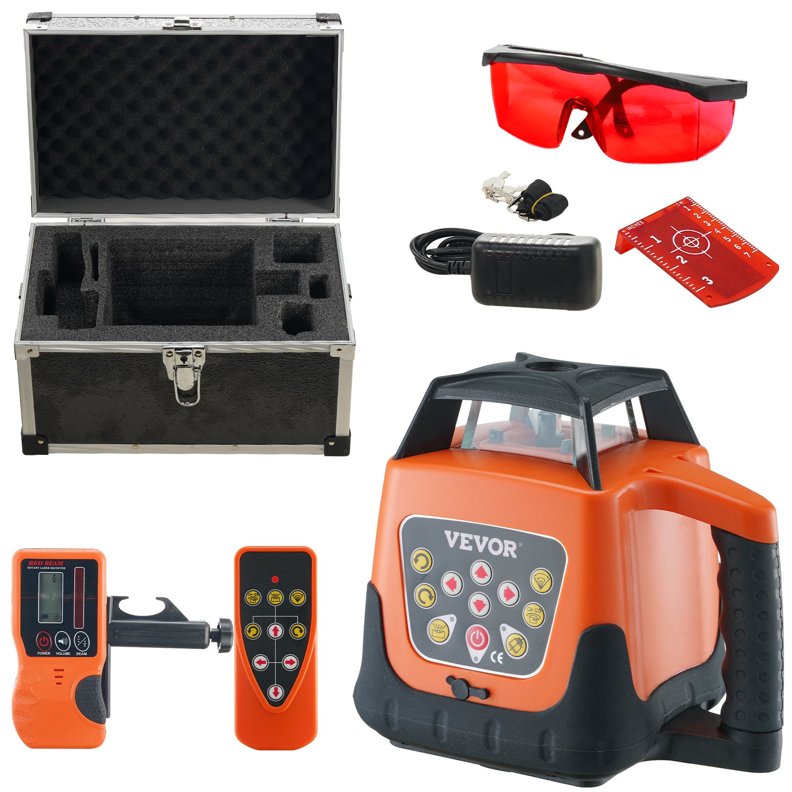
Unlock the full potential of your VEVOR Laser Level with our comprehensive product manual, available for download. Designed to assist both beginners and professionals, this manual covers every aspect of the 1650ft, 360-degree Leveling Red Cross Line Laser. With detailed instructions on setup, troubleshooting, and optimization, you’ll find it easier than ever to get the most accurate and efficient results from your laser level.
The manual provides step-by-step guidance on using the 5 rotation speeds and 4 scanning angles adjustment features, ensuring you can handle any project with precision. Whether adjusting the IP66 waterproof remote control or utilizing the self-leveling mode, our manual makes the process straightforward and stress-free.
Additionally, our manual highlights essential maintenance tips and battery management to prolong the life of your device. With this invaluable resource, you’ll have the confidence to tackle any task, knowing you have the support you need right at your fingertips.
VEVOR Laser Level User Manual
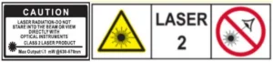
CAUTION
- While the product operates, avoid exposing your eyes to the emitting laser beam (red light source). Exposure to a laser beam for an extended time may be hazardous to your eyes.
- Glasses may be supplied in some of the laser tool kits. These are NOT certified safety glasses. These glasses are ONLY used to enhance the visibility in brighter environments or at greater distances from laser sources.
WARNING
- Read the Safety Instructions and User Manual thoroughly before using this product. All users must fully understand and adhere to these instructions.
- The following label/print samples are placed on the product to inform you of the laser class for your convenience and safety.
- Do not stare directly into the beam, view directly with optical instruments, or set up the laser at eye level.
- Do not disassemble the laser tool. There are no user-serviceable parts inside.
- Do not modify the laser in any way. Modifying the tool may result in hazardous Laser Radiation Exposure.
- Do not operate the laser around children or allow children to operate the laser. Serious eye injury may result. An exposure to the beam of a Class 2 laser is considered safe for a maximum of 0.25 seconds. Eyelid reflexes will normally provide adequate protection.
Functions
This instrument is equipped with a semiconductor diode with a wavelength of 532 nm, and the laser beam has supreme visibility. And the laser module of the tool will rotate freely to form a laser-scanning surface. Emitting direction of the rotary laser beam is illustrated as follows:
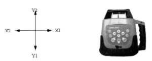
Introduction to the Laser Level
Main body
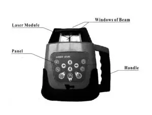
Panel
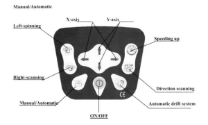
Utilities of Panel
- ON/OFF: Controlling the state of power.
- Power indicator: When it lights, the instrument is starting up.Otherwiseit isclosing down.
- Mode indicator: When it lights, the instrument levels manually. When it winks, it stays in alarm.(The slope of the instrument is out of range.)
- Key of the Automatic drift system model: Warns the user of a misaligned device
- Light of Automatic drift system model: When the light twinkles slowly, it is in the Automatic Drift System model. When the light twinkles quickly, the laser level will not level when shaken.
- Speeding up: Circling knob. Speed of scanning includes 5-knots:0-60- 120-300-6000 r.p.m
- Directional scanning: Circling knob. Angle of scanning includes 5levels:0-10°-45°-90, 180°
- Manual/Automatic: Controlling the mode of leveling.
- Left-spinning: Making the laser module step-move counter-clockwise, when the laser module is power off or the scanning direction is changed.
- Right-spinning: Making the laser module step-move clockwise, when the laser module is power off or it is scanning directionally.
- X-axis: Adjust the X-axis’s slope when the instrument stays in manual mode.
- Y-axis: Adjust the Y-axis’s slope when the instrument stays in manual mode.
Directions
Battery Installation
4×C-size Ni-MH Rechargeable batteries can be used in the instrument.
- Take down the battery case cover at the bottom of the instrument.
- Put the batteries into the case according to the right electrode.
- Lay the cover on the box, and then tighten all the screws.
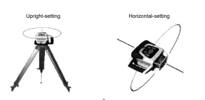
Instrument Placement
Horizontal scanning
Lay the instrument on the tripod or a stable flat surface, or even hang it on the wall. Set upright the instrument, and keep the slope of the instrument within the range from -5 ° to +5° 3.2.2
Vertical Scanning
Lay the instrument on the flat surface, and keep the slope of the instrument within the range from -5°to +5°
Operations
Power
- Press the Key ON/OFF to bring automatic leveling into function when the power indicator lights.
- When the power indicator lights up, it shows that the voltage of the batteries is insufficient. Then the rechargeable batteries need to be charged.
- Press the Key ON/OFF again to close the instrument when the power indicator goes out.
Leveling
Press the Key ON/OFF to bring automatic leveling into function when the laser beam begins to wink. After automatic leveling, the laser module will rotate right at a speed of 600 rpm.
If the instrument is placed improperly or the slope exceeds the range from -5 ° to +5°, the mode indicator and the laser beam will wink simultaneously.
Then place the instrument properly.
Notice: The instrument will close down automatically after a five-minute alarm.
Spinning
(1) Continuous Spinning
Press the Key. Speeding up to control the spinning speed of the laser module.If you press the key repeatedly, the spinning speed of the laser module will continuously change as follows:0-60-120-300-600-0 r.p.m.
(2) Stepping Spinning
Locate the Key Speeding-up at O r.p.m., the laser module will stop spinning. Press the key right-spinning, and the laser module will step-move clockwise. Then, if you press the Key Left-spinning, the laser module will step-move counter-clockwise.
Directional Scanning
- Press the Key Directional scanning; the laser module will scan directionally. Press the key repeatedly, the angle of scanning of the laser module will continuously change as follows: 0° -10°-45°-90°-180°-0°
- Press the Key Left-spinning or the Key Right-spinning to change the scanning direction.
Slope Adjustment
When the instrument is set upright to do horizontal scanning, the slope of the X-axis and Y-axis can be adjusted.
Press the Key Manual/Automatic when the mode indicator lights, and the instrument enters the manual leveling mode.
(1)Slope of X-axis
- Aim the X1-beam to the direction of the slope required to adjust, as depicted below:
- Press the Key←or →to move the laser beam up or down.
(2) Slope of Y-axis
- Aim the Y1-beam in the direction of the slope required to adjust.
- Press the Key ↑ or ↓ to move the laser beam up or down.
Notices: Press the Key Manual/Automatic again when the mode indicator goes out, and the instrument will enter the automatic leveling mode.
Power
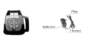
When the voltage indicator lights, the batteries needs to be charged immediately.Connecting the charger with AC, insert the plug of charger into the plug hole at the bottom of the instrument (As depicted above).
If the indicator of charger lights, it shows the batteries are being charged.
If the indicator light of the charger winks, it shows the course of recharging has ended.
Notices:
- Using the standard rechargeable batteries of the instrument, recharging will be finished within 7 hours,
- Power required for the charger: Frequency:50-60HZ; Voltage:85-265V.
- Charging and using of the instrument can progress simultaneously.
- If keeping the instrument in storage (or Leaving the instrument unused for a long time),the batteries (dry or rechargeable) need to be removed.
- Brand-new rechargeable batteries or long-time unused rechargeable batteries must be recharged and discharged three times to attain the requiredcapacity.
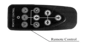
Remote
The remote of the instrument adopts the infrared technique. Aim the aperture of infrared ray to the instrument (as depicted below) to bring remote controlling into function (Available distance: indoor: 30M; outdoor: 20M).
The telecontrolling panel includes 9 keys; the indicator on the device will wink to show the operating signal has been sent out once pressing any key.
Laser Level Accuracey Checking
Horizontal-surface Checking
1. Place the instrument at the point of 50m in front of wall(or set a scaleplate at the point of 50m away from the instrument), and then adjust the level of the base approximately to aim the X1 to the wall (or scaleplate), as depicted below:
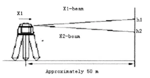
(2) After switching on the power, use the laser detector measuring the h¹ of X1- beam on the wall or scaleplate.
(3) Loose the screw of the tripod, and then turn around the instrument 180°to measure the h2 of X2 -beam on the wall or scale- plate. D-value between h1 and h2 ought to be less than 10mm. (4) Check the Y-beam in the same way.
Horizontal-line Checking
(1) Place the instrument between two walls with a distance of 30m(or two scaleplates with a distance of 30m).
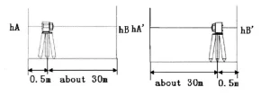
(2) Place the instrument according to horizontal setting and then adjust the instrument.
(3)Switch on the power, and then measure the middle point of the laser beam on the wall (or scaleplate):hA,hB and hA′,hB
(4) △1=hA-hA′, △2=hB-hB’
D-value between △1 and △2 ought to be less than 6mm.
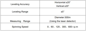
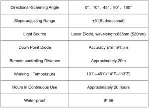
Specifications
Recommended For Your Project
VEVOR Laser Level, 1650ft, 360 Degree Self Leveling Red Cross Manual


Reviews
There are no reviews yet.